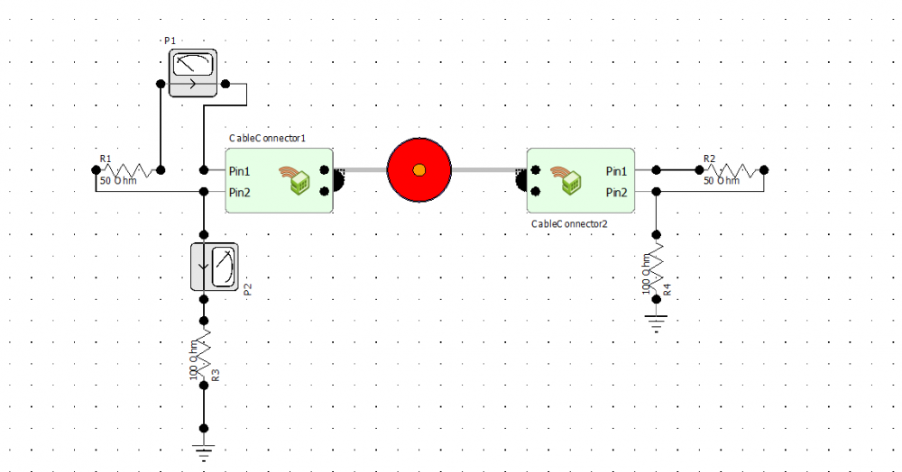
The terminals of shielded cable
what is the best terminal geometry of a coaxial cable so that to get high accuracy results ? please see the following figures
case 1 :
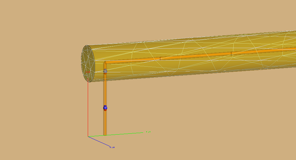
case 2 :
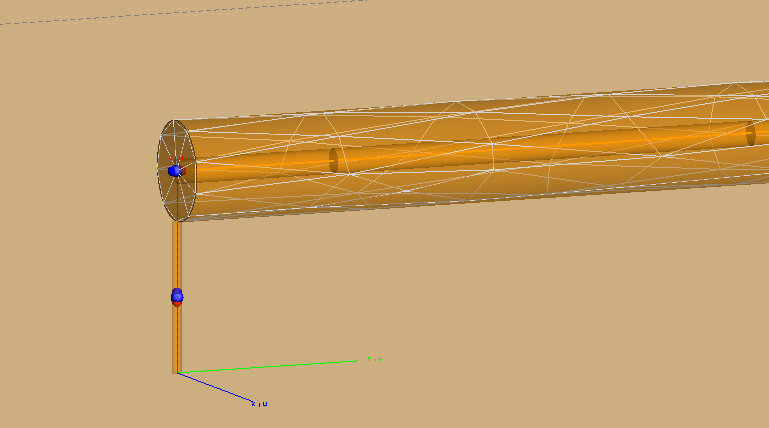
However, both results does not agree with TLM solution performed by FEKO. why? is the terminal connection geometry effect the results ??
TLM solution using transmission line model schelkunoff model for transfer impedance
Answers
-
Feko uses the thin wire approximation. You will not necessarily get accurate results by just specifying the wire radius. It only modifies the self impedance of the wires and will not necessarily accurately model the coupling to the shield, which is critically based on the physical spacing between the inner and outer conductors.
It would be better, although computationally more expensive, to model the center conductor as a cylinder meshed into triangles. You must ensure that the meshed triangle edge lengths are roughly the same as the spacing between the inner and outer conductor.
Secondly the radiation from the terminations can become significant if the the electrical length of the termination segments become large (so at high frequencies). This electrical length is not modeled in the MTL terminations. At higher frequencies you can compensate for the inductive effect by adding an equivalent capacitance.
0 -
thank you so much for your help. However, how can we mesh the cylinder into triangles with the edge lengths the same as the spacing between the inner and outer conductor ? what about the outer conductor connection to the ground? should i use wire approximation or cylindrical ?
0 -
>> However, how can we mesh the cylinder into triangles with the edge lengths the same as the spacing between the inner and outer conductor
Just apply a local mesh size on the inner cylinder face.
>> what about the outer conductor connection to the ground? should i use wire approximation or cylindrical?
You can use either. You will be adding stray inductance to ground with either of them. But at low frequencies this inductance will be very small.
0 -
thank you so much,
if i use cylinder wire, how can we add a load to it? should i use small segment wire to add a load ? or there is another way ?
also, what is stray inductance, how can i add it and how i should connected to the grounding wires?
thank you in advance.
0 -
0
-
You can add the inductance to a port on the wire that connects to the ground.
For a port on the cylinder, you can use the edge port. See e.g here below an edge port for a cylinder dipole. (Or you can make a small gap and use a short wire with a wire port.)
0 -
thank you so much for your help, you are a great helpful person
0