Importing geometry from Solidwork

ttttC
ttttC Altair Community Member
edited October 2020 in Community Q&A

Hi there. I have met a few problems with importing geometry from Solidwork.


As I am using the student version, I have imported solidwork file to CADFEKO in parasolid format.

I am looking for the inductance of the model so I have meshed the model and solved it to obtain the output file. 


In the output file, it only shows the capacitance of the model:

image.png.67971d9100b1f907f09897cf6cfd8c0c.png


Then, I have built a similar model using CADFEKO. But this time it shows the inductance of the model is 2.7uH. 

image.png.64bee7d8535200ccc77d8ae3c3e67280.png


The dimensions, model extent, voltage source, frequency used in both files are the same. I expected the results from both files would be similar.

At least both of them should have inductance shown in the output file.

Why there is such a big difference in the results? Is there anything I have done wrong?


<?xml version="1.0" encoding="UTF-8"?>image.png
Unable to find an attachment - read this blog

Tagged:

Answers

  • Mel
    Mel Altair Community Member
    edited March 2020

    Just looking at your two *.out files (you only attached only one model's cfx) I see 8700 triangles in the 'solidworks' model while the cadfeko model only has wire segments, and then only 155.

    The two meshes are way different from each other and therefore the results would be too.

  • ttttC
    ttttC Altair Community Member
    edited March 2020

    In my understanding, more triangles means the solution is more accurate. Am I correct?

    But I have built the model in real life and measured the inductance of the model. It is 2.68uH.

    Does it mean my mesh for the 'solidworks' model was incorrect?


  • Mel
    Mel Altair Community Member
    edited March 2020

    Imported CAD can often have issues in the geometry causing poor meshing.

    The triangle edges in the image below are not continuous and the edge port should cover the full circumference of the circular tube.

    port.png

  • ttttC
    ttttC Altair Community Member
    edited March 2020

    Is there any method for improving meshing?

    If the import CAD is a wire, is there a method to allow CADFEKO to recognize it as a wire so I could perform meshing by using wire segments instead of triangles?

    Or do you have any recommendations on improving the meshing for such model?

    thanks a lot!

  • Mel
    Mel Altair Community Member
    edited March 2020

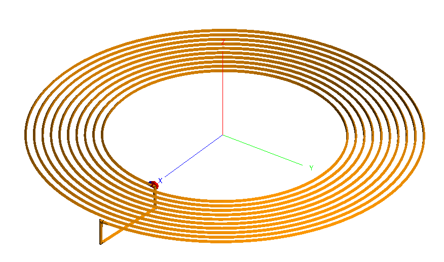
    The spiral coil.x_t imported into CADFEKO comes in as a wire. This will mesh into wire segments.

    <?xml version="1.0" encoding="UTF-8"?>image.png


    I am not sure where you obtained the triangular mesh.

  • ttttC
    ttttC Altair Community Member
    edited March 2020

    I am sorry I must have uploaded the wrong file. Attached should be the right one. 

    GeomImport1 is wire and GeomImport2 has edges and faces.

    Unable to find an attachment - read this blog

  • Mel
    Mel Altair Community Member
    edited March 2020

    The import contains a wire loop and loop made from a cylinder. 

    I deleted the wire loop part.


    For the disconnected faces, where the meshes don't align, select the two faces adjacent the disjoint, right-click to Copy (duplicate).

    Then select the two copied faces and click on Stitch.

    Then delete the two original faces from the original part.

    Then Union the Stitch with the original part (part where the two faces were deleted).


    I added an edge port as seen below and get 2.7 uH.


    Some images.

    edge_port.png


    two_faces.png

    disjointed_mesh.png


    disjointed_mesh_fixed.png

  • Mel
    Mel Altair Community Member
    edited March 2020

    Forgot to add, the model is electrically very small. Enable double precision for higher accuracy.

  • ttttC
    ttttC Altair Community Member
    edited March 2020

    May I ask how do you find those unaligned mesh? Or should I stitch all the faces together?

    Do I need to delete the edges?


    Moreover, I found that in POSTFEKO, the model will become cubical. Is this normal? 

    image.png.525de4e6b9b66cf1eef437ee07255a2f.png

  • ttttC
    ttttC Altair Community Member
    edited March 2020

    Sorry there is one more question. 

    I found these warnings in the output file:

    WARNING 510: Imaginary part of the impedance is large thus the real part will be inaccurate

    WARNING 509: Reactive power large thus real power is inaccurate


    Do they have a big impact on the results? Is there anything I can do with them?

  • Mel
    Mel Altair Community Member
    edited March 2020

    You must use double precision - enter the text in the search bar on the top right of cadfeko if you don't know where to enable this.

    The mesh will look 'cubical' if there are not enough triangles around the circumference of the tube.

    You can also view the mesh in CADFEKO by disabling the Overlay and Model view icons and only enabling the Simulation mesh view icon on the Display options tab.

    Connectivity can be viewed by clicking the Connectivity icon.

  • ttttC
    ttttC Altair Community Member
    edited March 2020

    Thank you so much for such a fast respond. 

    I did set double precision but the warning still remained. 

    But at least I have got the inductance as 2.7uH. Thanks a lot!

  • ttttC
    ttttC Altair Community Member
    edited March 2020

    But I have now met another problem. I am simulating the antenna which was fabricated on a pcb. So the cable is actually flat instead of cylindrical. 

    I have redrawn the whole antenna and try to simulate it. This time I have stitched all the faces and union them.

    The triangle edges was set to 0.001.

    However, I did not get the same result. I wonder if you have any idea.

    image.png.82cc8e0f16ee3b388e1bf7bd2f6d00b4.png

    Unable to find an attachment - read this blog

  • Mel
    Mel Altair Community Member
    edited March 2020

    Your port is incorrect, getting shorted out.

    Consider something like this:

    <?xml version="1.0" encoding="UTF-8"?>image.png

  • ttttC
    ttttC Altair Community Member
    edited April 2020

    I have got it! Thanks a lot:)