Hello
I work as a student in the sector of emc and would like to simulate a simple component measurement like yo can see in the link as a preview:
https://www.sae.org/publications/technical-papers/content/2020-01-1371/
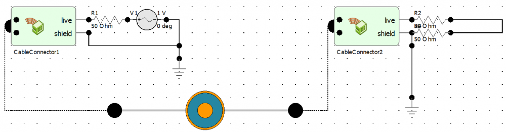
In difference to the study in the link i just use a simple power supply and as the consumer a resistor, which have a current and voltage probe.
I am working with feko for the first time and have achieved first results with cable laying and antenna placement&design, but in this case i dont get any result.
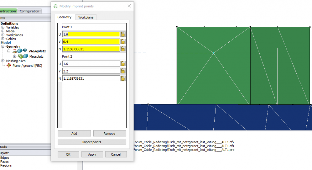
I think the main problem is in the 'cable reference direction' which i dont understand completly how to use it and in the faces of my geometry in the modell.
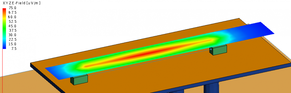
Like in the link i expect to see the electrical field over a coaxial cable which is power supllied and completed with the a resistor which is in my case a consumer as areplacement circuit.
I enclose my model and would appreciate any advice or reference.
This are the errors at validating the modell:
1)The following cable paths (that exist in a harness using the MTL solution method) terminate on a metallic triangle:
CablePath1
2)Dielectric faces may not be located on the interface of the planar Green's function.
Here my model:
<?xml version="1.0" encoding="UTF-8"?>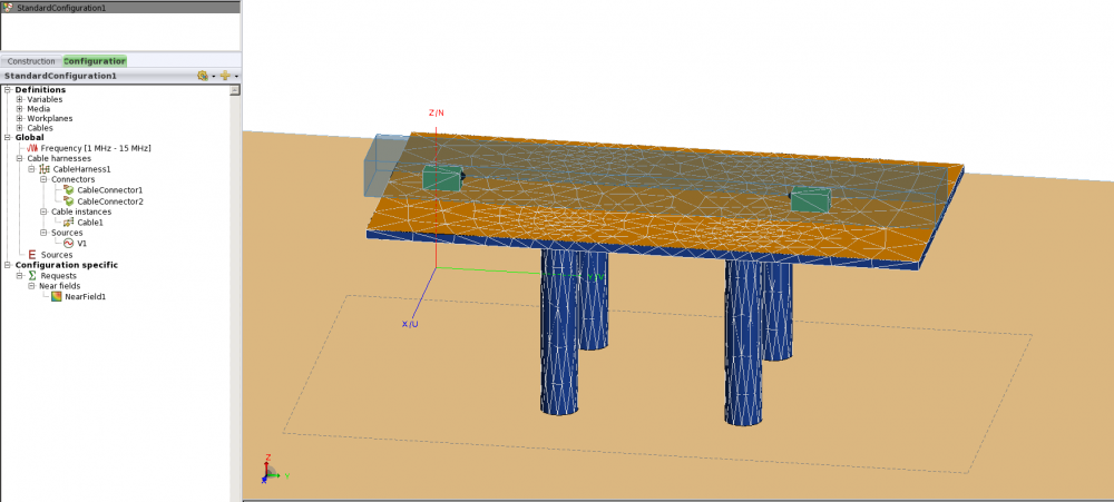
<?xml version="1.0" encoding="UTF-8"?>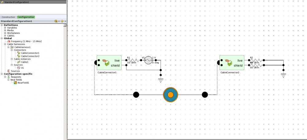
Thanks in advance.
Unable to find an attachment - read this blog