Plotting surface currents in CMA

RF Engineer
RF Engineer New Altair Community Member
edited October 2020 in Community Q&A

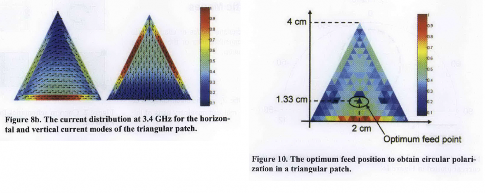
Hi! I want to design a circularly polarized antenna using CMA, for that I have to excite two orthogonal modes simultaneously. To locate feeding point to achieve circular polarization we need to plot surface currents of both degenerate modes simultaneously and feeding antenna at the point where surface current of both modes is maximum. I am trying to plot two surface currents but FEKO is not allowing me to plot them. Please help me plotting both currents simultaneously.  I have attached figures for the reference, 2nd figure is HFSS plot. 

HFSS allows you to plot surface currents of many modes simultaneously.

<?xml version="1.0" encoding="UTF-8"?>Cirular polarization.png
 

Tagged:

Answers

  • Wilco Strydom
    Wilco Strydom New Altair Community Member
    edited November 2018

    Hi RF Engineer,


    we need to plot surface currents of both degenerate modes simultaneously

    To do this you simply create two 3D Views in POSTFEKO and add the desired modal current to each.
    In order to view a (scaled) combination of modes you will have to resort to some scripting to combine the modes. Have a look at other threads discussing scripting, or work through the intro section and the example in the Example guide.


    and feeding antenna at the point where surface current of both modes is maximum

    From what I remember from this article and what is indicated in the images you attached, this is not what you want to do. For one, the excitation is at a point where the currents are equal but neither is at maximum. I also expect that you will want to model the complete patch setup with the feeding included, since this will affect the modes, and I would then also look at Modal Weighting Coefficients in order to ensure that the two modes can be excited equally. I thus expect you would set your script up to look at the difference between the two currents (scaled with MWC) and then look where this plot goes through zero.

    @Peter Futter can possibly confirm, but I don't think I've seen a case study where a CMA based design for a circularly polarized antenna has been illustrated in full. It would be interesting to see your results.

  • RF Engineer
    RF Engineer New Altair Community Member
    edited November 2018

    Hi RF Engineer,


    To do this you simply create two 3D Views in POSTFEKO and add the desired modal current to each.
    In order to view a (scaled) combination of modes you will have to resort to some scripting to combine the modes. Have a look at other threads discussing scripting, or work through the intro section and the example in the Example guide.


    From what I remember from this article and what is indicated in the images you attached, this is not what you want to do. For one, the excitation is at a point where the currents are equal but neither is at maximum. I also expect that you will want to model the complete patch setup with the feeding included, since this will affect the modes, and I would then also look at Modal Weighting Coefficients in order to ensure that the two modes can be excited equally. I thus expect you would set your script up to look at the difference between the two currents (scaled with MWC) and then look where this plot goes through zero.

    @Peter Futter can possibly confirm, but I don't think I've seen a case study where a CMA based design for a circularly polarized antenna has been illustrated in full. It would be interesting to see your results.

    yes you are right about that, currents of both modes must be equally strong at the feeding point. I am beginner so I don't have any idea about scripting , I have only started using CMA tool and I will be doing a detailed analysis of antenna to achieve circular polarization.