modal analysis of HMSIW slot antenna
Hi,
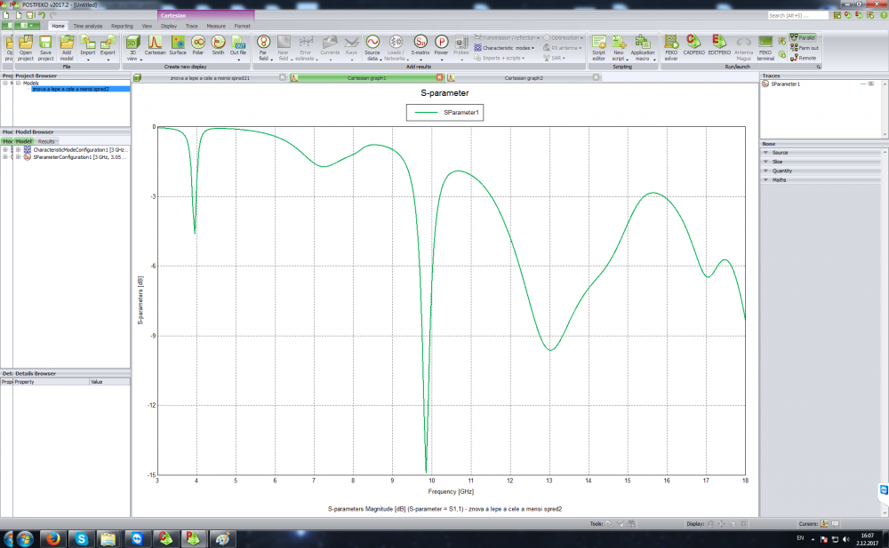
I have a HMSIW linearly polarized U-slot antenna (see attachment #1 and #2) tuned at 10 GHz (see attachment #3) and I would like to calculate a modal analysis. I am interesting in first 10 modes.
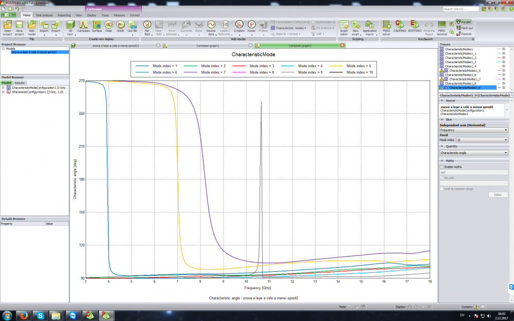
The antenna should operates in fundamental mode which is TE 0.5;0. Based on the results calculated by FEKO (see attachment #4), the antenna operates in the 7th mode which is not correct, the 6th and the 8th modes are not calculated at all and the 9th mode is some kind of artefact. I think the modal analysis is not correctly calculated at all.
Quick info about settings:
start frequency: 3 GHz
end frequency: 18 GHz
frequency step: 50 MHz (301 frequency samples)
number of modes to calculate: 100
model has infinite dielectric substrate (Arlon CuClad 217 with er = 2.17 and tan(alfa) is set to zero) and infinite ground plane
mesh is finer than mesh size: Fine setting (length of the edge is 0.5)
data storage precision: double precision
What I am doing wrong?
<?xml version="1.0" encoding="UTF-8"?>
Answers
-
Hi Banana,
I am currently rerunning your simulations to mode 6 and 8.
The antenna should operates in fundamental mode which is TE 0.5;0. Based on the results calculated by FEKO (see attachment #4), the antenna operates in the 7th mode which is not correct
the mode numbers are assigned based on the first simulation frequency sorting - so the numbering is somewhat arbitrary. I would suggest that you rather check the modal current distribution of mode 7 at the resonance that you are interested in to verify that it is the mode that you expect.
0 -
Attached is the plot of the modal significance as well as the modal weighting coefficient plotted in dB (I added a voltage source to your port). In both plots I have hidden the insignificant modes, which are not necessarily the same in both cases. What you can see in both plot is classical for wideband CMA analysis - the modal presence increases as the electrical size of the antenna increases. Similarly it becomes more difficult to isolate and excite as specific mode on the structure - more modes are excited in the upper part of the band.
The plots can be generated automatically using the CMA macro plotter:
https://connect.altair.com/CP/script-list.html
0 -
Thank you for answer, I really appreciate your help. I am currently recalculating the antenna. There is some error in the results and the surface currents won't show up. I expect that the results will be calculated on friday the 8th.
Based on the calculated modal significance, the antenna works in the 4th mode? What if I set the start frequency of the CMA to 9 Ghz, the 4th mode will becomes to 1st mode?0 -
Based on the calculated modal significance, the antenna works in the 4th mode? What if I set the start frequency of the CMA to 9 Ghz, the 4th mode will becomes to 1st mode?
From the modal significance plot and your characteristic angle plot it looks like mode 7 will become mode 1.
results will be calculated on friday the 8th.
Something that you can try to speed up the simulation is to remove the substrate and just simulate the metallic part of the antenna. It will shift the modal resonances slightly in frequency but other than that the effect should be small. This is a good starting point for the modal analysis, but in the end you might want to simulate the full structure including the substrate to get the exact response.
0 -
Hi Peter,
I recalculated the simulations in order to obtain farfield, currents distribution and modal weighting coefficient. The POSTFEKO shows only first 9 modes. I used the CMA plotter. In the CADFEKO, the number of modes to calculate is set to 100 but it is not enough. In your model, did you change that number to higher number? Or did you change anything except the voltage port?
0 -
It looks like there was a problem calculating some of the modes? Have you checked the .out file for warnings or errors?
0 -
There is 1 notice and 1 warning:
NOTICE 37561: Characteristic mode analysis may require a finer mesh compared to standard full-wave solution techniques, to accurately capture higher order mode behaviour
The model has finer mesh than the 'mesh size:fine' setting. Triangle edge length is set to 0.5.WARNING 37630: The eigenmodes calculated for CMA are not all orthogonal.
It could be fixed by switching to 'Data storage precision: double precision' in Solver settings. Which I already did it.
What do you suggest?
0 -
can you please attach the .cfx file so that I can have a look at it?
0 -
0
-
Hi @banana22
sorry for the delay getting back to you.
the only difference between my simulation model and yours was that I increased the number of frequency point to 301 points in the band, 50 MHz steps. Then I only requested 10 modes - whenever FEKO reaches a discontinuity in the mode tracking, additional modes will be tracked. That is why I am able to plot modes numbers up to mode number 57 even though I only requested 10 modes.
0 -
Hi Peter,
I am currently recalculating the CMA according to yours settings. I will let you know, when it be done.
0 -
-
Excellent, glad to hear that everything worked out!
0 -
sir,i'm a chinese user,for some unkown reasons, i can't download the CMA plotter ,could send me one to 497408506@qq.com ,thx!
0 -
Altair Forum User said:
Excellent, glad to hear that everything worked out!
sir,i'm a chinese user,for some unkown reasons, i can't download the CMA plotter ,could send me one to 497408506@qq.com ,thx!
0 -
I am trying to plot the Modal Weighting Coefficients and I am getting this error(error.pnj).
Not sure what am I doing wrong
0