Mesh transition techniques
Hi all,
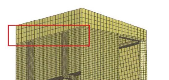
I would like to make fine mesh in the critical area of the model and coarse mesh in general areas. I have seen one model how this was done using method I would like to get to know- see the attached figure.
It seems that on the shared edge 2 surfaces are connected but with each second node unconnected. Does anyone know how to do this? It is important that 2 surfaces remains connected.
I have read about mesh transition techniques in Hyperworks Student Guide but it does not say anything about this method.
Thanks.
Answers
-
Hi, Gig
In manual mesh work, you can choos 'break connectivity' when refine (remesh) elems with half global size,
and then you use replace function to stick the nodes on transition line
Usually if the transition mesh is that you want before push it to solver, it's better to remove all free-edge (means the nodes must be connected, just need some tria elems)
But if you want the mesh become finer in real-time when solving, you can activate adaptive-mesh (if solver supported), the critical area will be automatically refined to get more detail results
0 -
-
Hi,
Thank you for your replies. Interesting Nguyen, I have never seen this kind of method. Actually I am using 2D shell elements- linear static analysis, how appropriate is this method? How does it affect the results? Probably it is advisable to do this outside your critical area?
Actually I have been told that 'TIED INTERFACE' is the feature I am looking for. Does anyone know, it this method possible in HyperMesh- RADIOSS Bulk Data Format?
0 -
Altair Forum User said:
Hi,
Thank you for your replies. Interesting Nguyen, I have never seen this kind of method. Actually I am using 2D shell elements- linear static analysis, how appropriate is this method? How does it affect the results? Probably it is advisable to do this outside your critical area?
Actually I have been told that 'TIED INTERFACE' is the feature I am looking for. Does anyone know, it this method possible in HyperMesh- RADIOSS Bulk Data Format?
Yeah, the transition area should be found far enough from critical area. I used this technique to avoir to use 'sticking' method for non-coincident meshes. This transition technique should be ok for 2D or 3D mesh. Of course, with 2D the meshing work is simplier very much.
I don't know about RADIOSS solver. But IMHO, this technique should be ok for any solver accepting 'pyramids' elements (for 3D meshing case).
0 -
Hi gig,
It is possible to define 'TIED INTERFACE' in HyperMesh-RADIOSS Bulk.
You can refer this tutorial about defining interface. The only difference in your problem is that ;contact type should be 'FREEZE' not 'SLIDE' .
file:///C:/Program%20Files/Altair/11.0/help/hwtut/hwtut.htm?rd_2100_nlstat_analysis.htm
0 -
Hi all,
I am quite new to the entire FEA area, so I hope someone can help me. I have already worked through the entire HyperMesh tutorial, but I am still stuck.
The problem addressed here is the kind of the problem I am facing as well. Working with an ABAQUS profile,I want to have a ' smooth transition' (in terms of element density) between a coarse mesh (elm size, say, 6) and a fine mesh (elm size 1). If I use the replace function, does it matter if the elements become destroyed and/or deformed?
Also, if I use 2D automesh with a somewhat larger element size, it seems impossible to follow the surface contours, what can I do about this?
0 -
-
Hi newbie,
I think it is possible by meshing the surfaces with different order(Parabolic to linear),,..
That is, If u see your 'ATTACHED THUMBNAIL' The upper layer was meshed with second order quard elements (ELEMENT SIZE= X)
and the bottom one was done by First order quard element (ELEMENT SIZE= X/2).
Note: Many theoretical books do not support direct connection between linear and parabolic elements as shown (your Attached thumbnail).
But we can found very little effect in particular on stress magnitude provided the connection is carried out away from the critical location.
0 -
Thank you for your replies!
Does the subdivision into many small domains affect the result after calculation?
I have enclosed two images showing what I am working on, it IS necessary to have the same element density on the edge, right? and what about element density on the edge between two components, should these be exactly the same? (i.e. upper and lower vertebra?) Is this what they often call contact problems?
0 -
Subdivision will not affect the results.. (google about the mesh/FE convergence).. More finer the mesh/domains run time is higher thats all..
Shared edge should have same density.. else you will miss the mesh continuity..
Between two models or parts contacts can be modelled (to study how the two interact with each other during touching).. In this scenario, continuity is not a issue.. as you give a contact definition between two dissimilar mesh sizes.. Its advisable to have same mesh to avoid convergence issues.. else its ok..
0 -