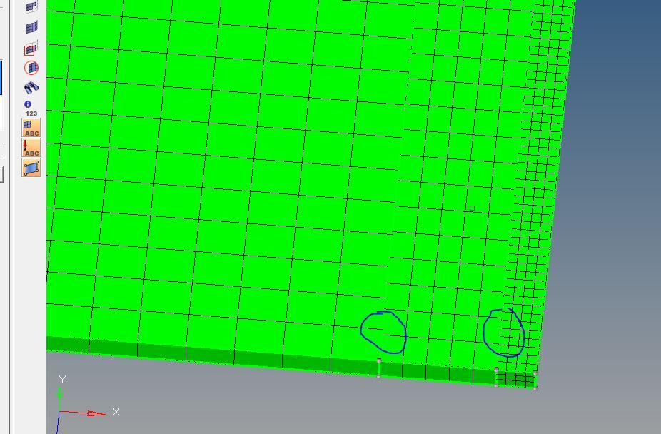
connecting nodes of different mesh size
I have 3 rectangular solids of dimensions 250*52*1.5 ,250*6*1.5 and 250*2*1.5 mm respectively. I need a refinement of 2.5,1.25 and .5 respectively. But when I am using solid map option for meshing solids, though I am getting the refinement as needed, nodes of meshes at the shared edges are not getting connected as shown in the figure attached. so how can i give transition edges at the shared boundaries so that nodes are connected properly. ?? Thanks
Answers
-
When the node count is different you can use 'ends only' with just 'elements to drag' and the 'destination surface'.
As a side note, A cube for instance with say 5 elements in one side and 10 elements in its opposite side, cannot be mapped with solid elements generally, this is physically impossible while maintaining connectivity !
0 -
thanks rahul. I used 2-d automesh for .5mm element size(hex mesh) in one surface and 2.5mm in a parallel surface. Is their any option to connect these two surface meshed using tetra or any other elements other than hex.?? when using 'ends only' options, element type is not being asked!!!!
0 -
I tried as u said with the 'match existing mesh checked' in 3-d tetra mesh. but still nodes of solids on both sides did not connect to middle one as shown in figure attached. I guess may be I did some mistakes in the initial stage. These are the steps I did so far. Please check if something went wrong
1)imported 3 solids into hypermesh
2)used geomtery-solids command created a fine solid
3)3-d- solidmap -one volume- meshed two of the end solids with 5 and .5mm
4)did 3d-tetra-volumetetra to mesh middle surface
0 -
Altair Forum User said:
I have 3 rectangular solids of dimensions 250*52*1.5 ,250*6*1.5 and 250*2*1.5 mm respectively. I need a refinement of 2.5,1.25 and .5 respectively. But when I am using solid map option for meshing solids, though I am getting the refinement as needed, nodes of meshes at the shared edges are not getting connected as shown in the figure attached. so how can i give transition edges at the shared boundaries so that nodes are connected properly. ?? Thanks
Hi,
Here is my example, see screenshot.
And here is my model HM: https://dl.dropboxusercontent.com/u/7959896/HW/plate.hm
Maybe this can give you some idea.
HTH,
0 -
Thank you Ngyugen. The picture what you showed is exactly what I was trying to reach. But I am not been able to reach there so far. And Unfortunately I am not able to open the file which you sent, it is showing 'file is not backwardly compatible with this version'. My version is 11.0. Could you please tell me if there is any mistakes in the steps i mentioned in last reply. (P.s here out of 3 solids middle solid I have used for getting a transition).
Thanks
0 -
Here is HM 11.* model : https://dl.dropboxusercontent.com/u/7959896/HW/plate_11.hm
0 -
Thanks Nguyen. Now I am able to view the model. As of now i can just see the components. Is there any option in hypermesh to see the various steps involved in creating this? If not available could you brief the steps involved. Sorry for shooting so many questions.
0 -
With some meshing experiences, you can make the same mesh by following my example.
Maybe I'll make a small tutorial later, when I have some free time.
0 -
Hello,
I am rather new to the entire FEA area and I need to have a fine mesh in the middle of the volume. Looking at these posts, I see that what you have,
on this image , is what I need.
Links above are not availables now, so, could it be the possibility that you pass me an example with few indications?. That would be so great for me.
Thanks in advance for your support
0 -
-
Many thaks Rahul, I will try and see if I am able to do it. I will come back.
0