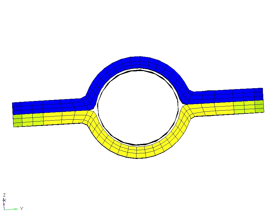
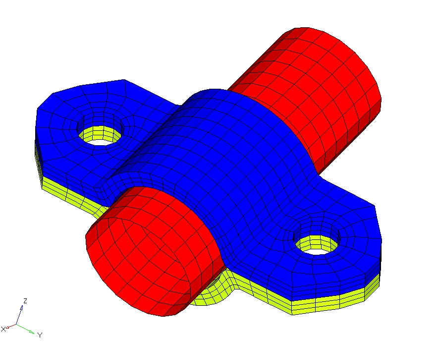
How to connect Solid and Shell mesh in the assembly shown below?

Altair Forum User
Altair Forum User
Altair Employee
edited October 2020 in Community Q&A

There is a small gap in the FE model because, the tube passing through the bracket at the middle is modelled as shell elements at the mid surface.


In real case,only there is friction due to tightening of bolts at either ends of the clamps.


What is the best practice to connect these meshes?

<?xml version="1.0" encoding="UTF-8"?>image194.jpg
 

<?xml version="1.0" encoding="UTF-8"?>image191.jpg

Tagged:

Answers

  • Altair Forum User
    Altair Forum User
    Altair Employee
    edited November 2016

    Hi Prashanth,


    You can use rigids to connect shell and solid elements.


  • Altair Forum User
    Altair Forum User
    Altair Employee
    edited November 2016

    @Prakash Pagadala


    Is it OK to connect the nodes directly via rigids? Some other sources mentioned that it is good practice to extract face of 3D element and connect it with the existing shell mesh via rigids. What is your view on this?


    Then, what thickness and properties should I assign to the extracted faces?


    Also, If I offset the shell mesh of the tube outwards, such that its outer face matches with the inner faces of the clamps, and add the whole thickness inward, can i equivalence the nodes between the clamp and the tube?

    If not what would be the best approach?


    Thanks in advance.

    <?xml version="1.0" encoding="UTF-8"?>image195.jpg

  • Altair Forum User
    Altair Forum User
    Altair Employee
    edited November 2016

    Hi @SKGPrashanth ,

    1.  If you directly connect shell elements and 3d elements by rigid elements, you may get an error because 2d shell elements have 6 Degrees of freedom and 3d solid elements have 3 degrees of freedom, because of this reason if you extract the face of the 3d elements then this face elements are directly connected with the 3d solid elements and compensate that 6 degrees of freedom. You can give negligible thickness to that face elements ex: 0.01 mm and PSHELL as a property with any dummy material. (By default AUTOSPC card is ON, that remove this 3 extra degree of freedom of shell when it is in contact with solid, but in general it is not recommended to connect solid and shell elements directly by rigid elements. It may leads you to in correct behavior of your system).
    2. Regarding the equivalence of the nodes, it simply means your outer surface of the tube is directly connected with inner surface elements faces of the brackets and you don't get any friction effect. Another problem is that your original dimension of the pipe may change (i don't know exact geometry but may be) that leads to incorrect distribution of the stresses and displacement.
    3. you can model pipe as 3d solid elements and create contact pair between them, that will also take in to consider the friction between the components.
    4. Regarding Best Approach, There is nothing like best approach in FEA. The only thing that matters is how well you capture the physics of your system. For the same system your model will change if you are interested to study it with respect to strength, with respect to vibration, with respect to multi-body dynamics, with respect to fatigue or other non-linear analysis.

    In your case, please describe the purpose of this analysis then i think i can help you to decide how to connect the two components.


    By the way, your mesh is really nice, can you please share with me the methodology that you adept to generate the mesh.


    Thank you...

    Have a Nice Day...


  • Altair Forum User
    Altair Forum User
    Altair Employee
    edited November 2020

    Is it OK to connect the nodes directly via rigids? Some other sources mentioned that it is good practice to extract face of 3D element and connect it with the existing shell mesh via rigids. What is your view on this?

    I see there is gap between shell and solid elements and that is why I suggested to use rigids. Using RIGIDS directly on solid elements to connect shell elements will not error out as the rotational DoFs on solid elements will be removed automatically in OpriStruct and this will be written in output file as a warning message. You can also use a layer of shell elements on top of solid elements but give a thickness as low as possible as this may impact your results.

    Also, If I offset the shell mesh of the tube outwards, such that its outer face matches with the inner faces of the clamps, and add the whole thickness inward, can i equivalence the nodes between the clamp and the tube?

    You can equivalence by doing an offset. But make sure you are not changing the dimensions of the clamp.

    Unable to find an attachment - read this blog