mesh quality

Altair Forum User
Altair Forum User
Altair Employee
edited October 2020 in Community Q&A

dear all,

I am trying to simulate tensile test in hyperworks. For meshing I am using 2D element because it is a tensile specimen made of sheet.


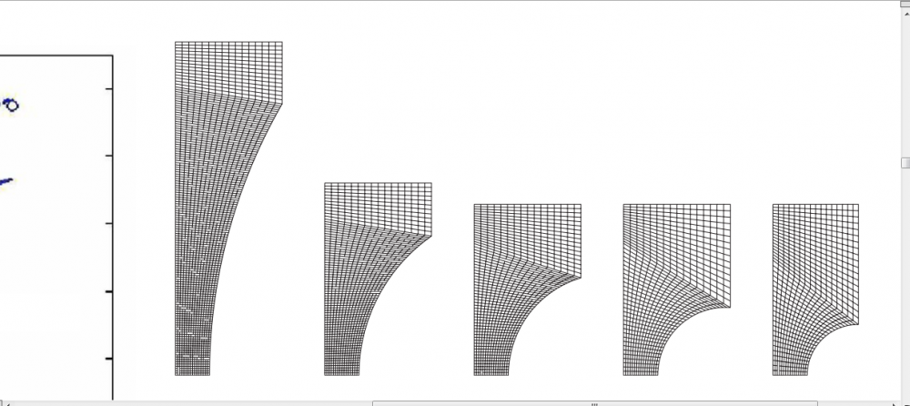
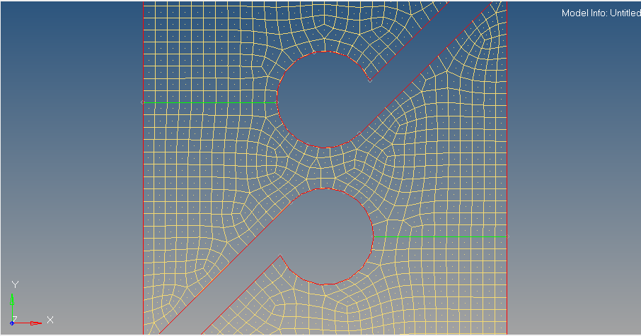
I am very much concerned about quality of mesh, because when i am using automesh command it generates very irregular mesh. I have seen many papers in which meshing is very fine in critical area and the quality of mesh is also good (transition of mesh).

Geometry of specimen is complex because im using modified specimen for simulating shear fracture.


Can anyone suggest me that how I can improve mesh quality near the center of the specimen and i also want to fine meshing near center.

I have read about mesh transition but I don't know how to do it in my case.

I have attached the image of mesh used by others and also mesh generated by auto mesh in my case. I have taken mesh size 1.

please, help me.

<?xml version="1.0" encoding="UTF-8"?>Untitled.png
<?xml version="1.0" encoding="UTF-8"?>Untitled1.png

Tagged:

Answers

  • Rahul Rajan_21763
    Rahul Rajan_21763 New Altair Community Member
    edited March 2016

    Hi,

    Do you want only quad elements?


    Regards

    Rahul R

  • Altair Forum User
    Altair Forum User
    Altair Employee
    edited March 2016

    Thank you for reply.

    I have also tried with Tria element and with mixed elements to. But the quality was not good in both cases.Can you suggest me which element will be good for this simulation.

    How I can mesh if want quad elements only?


    Thanks and Regards,

    Abhishek 

  • Rahul Rajan_21763
    Rahul Rajan_21763 New Altair Community Member
    edited March 2016

    What type of analysis you want to perform?


    Regards

    Rahul R

  • Altair Forum User
    Altair Forum User
    Altair Employee
    edited March 2016

    I want to simulate a tensile test for shear fracture with this modified geometry of specimen.

  • Rahul Rajan_21763
    Rahul Rajan_21763 New Altair Community Member
    edited March 2016

    Is this a axisymmetric model or just same as above shared snapshot?


    Regards

    Rahul R

  • Altair Forum User
    Altair Forum User
    Altair Employee
    edited March 2016

    It is the same model. I have attached the image of the CAD model of geometry.

    <?xml version="1.0" encoding="UTF-8"?>Untitled.png

  • Rahul Rajan_21763
    Rahul Rajan_21763 New Altair Community Member
    edited March 2016

    I feel keeping quad elements near to critical region is ok for analysis.Could you share the model file?


    Regards

    Rahul R

  • Altair Forum User
    Altair Forum User
    Altair Employee
    edited March 2016

    I have also tried with 3D auto meshing but computation time was too much. So I decided to use shell element. 

  • Altair Forum User
    Altair Forum User
    Altair Employee
    edited March 2016

    Which model file .hm or you want .igs file of this model?

  • Rahul Rajan_21763
    Rahul Rajan_21763 New Altair Community Member
    edited March 2016

    share both.

    Regards

    Rahul R

  • Altair Forum User
    Altair Forum User
    Altair Employee
    edited March 2016

    Please find the .igs file of this model.


    Pure shear simulation.igs is correct file which I want to simulate. 

    Unable to find an attachment - read this blog

  • Altair Forum User
    Altair Forum User
    Altair Employee
    edited November 2020

    This is the .hm file and .h3d file of previous simulation result.

    Unable to find an attachment - read this blog

  • Altair Forum User
    Altair Forum User
    Altair Employee
    edited March 2016

    <?xml version="1.0" encoding="UTF-8"?>tensile_pureshear.png

  • Altair Forum User
    Altair Forum User
    Altair Employee
    edited March 2016

    Thank you.

    I think that is the previous one which I have simulated. In this simulation I have generated the mesh with auto mesh and mesh size was 2.


    Please find the attached image which I have found in one of the research paper for similar simulation but they used solid element.

    <?xml version="1.0" encoding="UTF-8"?>shear.jpg

  • Rahul Rajan_21763
    Rahul Rajan_21763 New Altair Community Member
    edited March 2016

    Hi,

    I just checked results and mesh is distorting because of load and element size.Make some changes near critical region as suggested in above post.

    Using automesh option you can change the density along critical region.


    Regards

    Rahul R 

  • Altair Forum User
    Altair Forum User
    Altair Employee
    edited March 2016

    Thank you for your suggestions.

    I had tried to increase the mesh density near critical region but im not sure about the quality of mesh generated near critical region.


    Can you suggest me how I can mesh in same manner which I have attached with my previous message. 

  • Rahul Rajan_21763
    Rahul Rajan_21763 New Altair Community Member
    edited March 2016

    Did you try with Ruled option under 2D page?


    Regards

    Rahul R

  • Altair Forum User
    Altair Forum User
    Altair Employee
    edited March 2016

    Should I use shell element or I should go for solid element.

  • Altair Forum User
    Altair Forum User
    Altair Employee
    edited November 2020

    Here's my test. This mesh will give you good enough results.

    <?xml version="1.0" encoding="UTF-8"?>tensile_pureshear_QNGUYENDAI.png

    Unable to find an attachment - read this blog

  • Altair Forum User
    Altair Forum User
    Altair Employee
    edited March 2016

    Thank you very much for your reply.

    Can you explain the steps so that I can understand the logic behind this As per my knowledge this is mesh transition. Because I have 2-3 more geometry of different specimen for which I have to perform the same.


    Thanks and Regards-

    Abhishek

  • Altair Forum User
    Altair Forum User
    Altair Employee
    edited March 2016
    • Try to understand the physical behaviour
    • Identify 'critical' zones
    • Geometrical works to divise geometry into many sub-domains: critical, transitory, normal,...
    • Identify mesh size of critical zone, size of normal zone,...
    • Click, click & click over Hypermesh and you got the mesh

    Good luck!

  • Altair Forum User
    Altair Forum User
    Altair Employee
    edited March 2016

    Here's my test. This mesh will give you good enough results.

    <?xml version="1.0" encoding="UTF-8"?>tensile_pureshear_QNGUYENDAI.png


    Thank you for your help. But your .hm file is not supporting in my hypermesh it shows the message ' The file is not backwardly compatible with this version'


    I am using HyperMesh v12.0 for my analysis.

    Unable to find an attachment - read this blog

  • Altair Forum User
    Altair Forum User
    Altair Employee
    edited March 2016

    Did you try with Ruled option under 2D page?


    Regards

    Rahul R

    No I had not tried with ruled option in 2D page. Can you explain about this?

  • Altair Forum User
    Altair Forum User
    Altair Employee
    edited March 2016


    Thank you for your help. But your .hm file is not supporting in my hypermesh it shows the message ' The file is not backwardly compatible with this version'


    I am using HyperMesh v12.0 for my analysis.

    Sorry, I'm using HM v13.0

  • Altair Forum User
    Altair Forum User
    Altair Employee
    edited March 2016

    Sorry, I'm using HM v13.0

    I think you have created an arc near critical region. I have stared using HyperMesh just few days back. So it is totally new for me.I am facing difficulty in dividing the geometry in different regions.  

  • Altair Forum User
    Altair Forum User
    Altair Employee
    edited March 2016

    Have a look at my screenshot:

    (Just started 'few days', so you have all time to learn that. Good luck!)

    <?xml version="1.0" encoding="UTF-8"?>tensile_pureshear_QNGUYENDAI_sub-domains.png