How to use the weld seam in 1D connectors

Altair Forum User
Altair Forum User
Altair Employee
edited October 2020 in Community Q&A

Dear All,

I want to ask about weld seam application, please see my picture below.


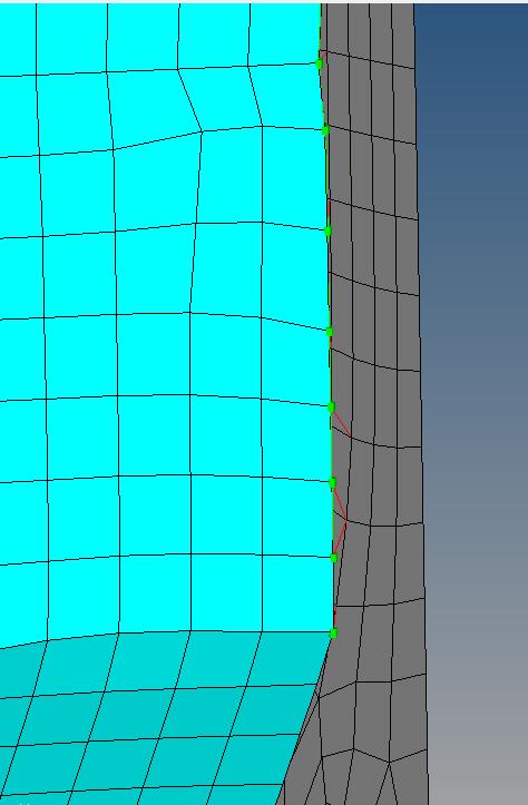
figure1, I want to connect the elements in two components to simulate the weld seam.


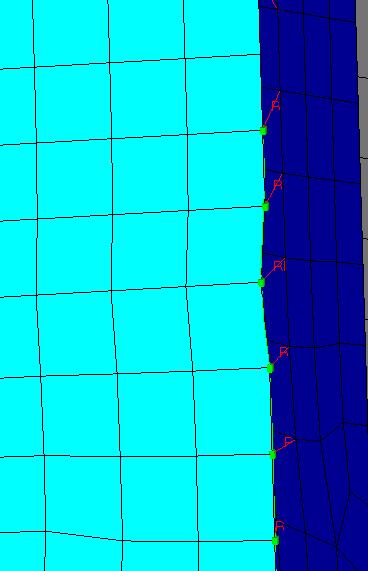
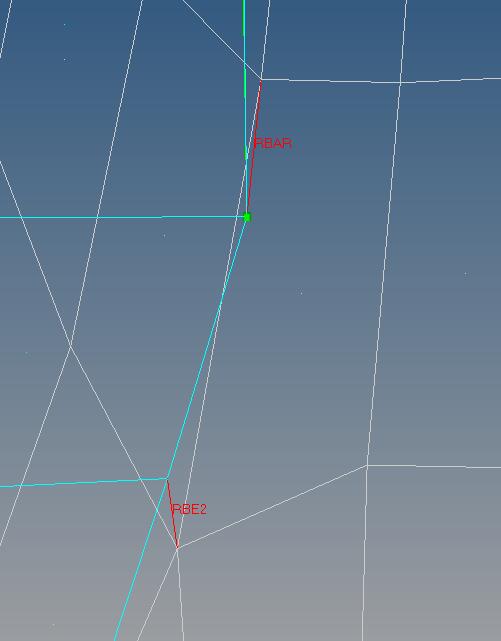
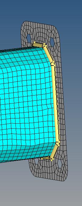
figure2,3.I use the 1D connectors seam application to create the seam weld.But there is a node with two REAR which leads to the error when solving the case.The acceptable model is one node connect with one REAR just as figure4.


I want to know how to avoid appearing the condition as figure 3 and to create the correct model as figure 4.


I have some confusing in RBE2 and RBAR, What different between in them?


Best regards,

Little_key


<?xml version="1.0" encoding="UTF-8"?>1.jpg
<?xml version="1.0" encoding="UTF-8"?>2.jpg

<?xml version="1.0" encoding="UTF-8"?>3.jpg

<?xml version="1.0" encoding="UTF-8"?>4.jpg

<?xml version="1.0" encoding="UTF-8"?>5.jpg

Tagged:

Answers

  • Altair Forum User
    Altair Forum User
    Altair Employee
    edited June 2017

    Hi,

    Can you try creating this spotweld from 1D>Connectors>Spot panel instead of Seam panel. And in Options menu of spotweld check on non normal projection and try creating the same.

    Regarding RBE2 and rbar elements, RBE2 is an infinitely stiff element, with dependent and independent nodes, whereas RBAR has only 2 nodes, so it's not as useful if you want to model a bolt, or attach with multiple nodes.These elements are defined based on applications specifically.

    I recommend you to go through http://www.altairuniversity.com/modeling/meshing-2/1d-2/ which explains all the concepts on 1D modelling.

  • Altair Forum User
    Altair Forum User
    Altair Employee
    edited June 2017

    Hi,


    Try with 'Find Nearest Node' option in weld panel. 

    <?xml version="1.0" encoding="UTF-8"?>SeamWeld.PNG

  • Altair Forum User
    Altair Forum User
    Altair Employee
    edited June 2017

    Hi,

    Can you try creating this spotweld from 1D>Connectors>Spot panel instead of Seam panel. And in Options menu of spotweld check on non normal projection and try creating the same.

    Regarding RBE2 and rbar elements, RBE2 is an infinitely stiff element, with dependent and independent nodes, whereas RBAR has only 2 nodes, so it's not as useful if you want to model a bolt, or attach with multiple nodes.These elements are defined based on applications specifically.

    I recommend you to go through http://www.altairuniversity.com/modeling/meshing-2/1d-2/ which explains all the concepts on 1D modelling.

    6

    Thanks at first.

    there are other problems:

    1.I want to know that how can we simulate the weld seam of cars with the hypermesh elements.Is it right that use spot weld or seam weld elements to simulate?

    2.I want to know why that. I assign the property to the connectors,  the component's mass is zero. why? Is it prove that i have not assigned the property to the seam weld correctly?


    thank you !


  • Altair Forum User
    Altair Forum User
    Altair Employee
    edited June 2017

    Hi,


    Try with 'Find Nearest Node' option in weld panel. 

    <?xml version="1.0" encoding="UTF-8"?>SeamWeld.PNG

    Thank you at first.

    I make the spacing value bigger than the element size so the number of connectors is less than the element nodes.It avoids the two connector's RBAR connect to the same node.But this lead to some nodes without RBEA.If i want to simulate the weld seam, must all the nodes on the edge(componentA ) are connected with componentB? 

  • Altair Forum User
    Altair Forum User
    Altair Employee
    edited June 2017

    Hi,


    1.I want to know that how can we simulate the weld seam of cars with the hypermesh elements.Is it right that use spot weld or seam weld elements to simulate?

    2.I want to know why that. I assign the property to the connectors,  the component's mass is zero. why? Is it prove that i have not assigned the property to the seam weld correctly?


    1. You can create spot welds for the same. Please go through this webinar https://www.youtube.com/watch?v=fNc9oVVkBa8&index=2&list=PL1u26y75SCrA_BOCLaSewVCNY7xRvCTnA which shows the steps for the same.


    2. You need to assign property for the same as in some cases if we want to apply a rupture criteria for the welds we can assign those through these property cards. If we are selecting a spring element, we have to specify the stiffness parameters also.


  • Altair Forum User
    Altair Forum User
    Altair Employee
    edited June 2017

    2.I want to know why that. I assign the property to the connectors,  the component's mass is zero. why? Is it prove that i have not assigned the property to the seam weld correctly?

    Can you check whether material is assigned to 1D elements? Also check the material data. Density is required to calculate mass. 

  • Altair Forum User
    Altair Forum User
    Altair Employee
    edited October 2017

    connections confuse me ?How to decide which one to take?

  • Altair Forum User
    Altair Forum User
    Altair Employee
    edited October 2017

    Hi,

    In general connectors are geometric entities that define connections between other entities.

    Please go through https://altairuniversity.com/wp-content/uploads/2012/04/HM_1D_Extract.pdf and https://altairuniversity.com/wp-content/uploads/2013/05/HTC2012_Connector_Training.pdf which are documents on connectors and explains them in detail.