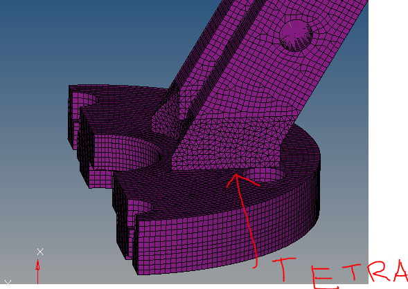
Component meshed with tetra and exa
Hi. I had to mesh a component. I cut the solid in some parts and I meshed one of them with tetra elements (as you can see in the photo) because I wasn't able to mesh it using exa elements. I meshed the remaining parts with exa elements. Does it make any sense to mesh some parts with tetra and other ones with exa? Should I have meshed the whole component with tetra elements? Thank you.
Answers
-
-
Hi Prakash, thank you for answering me. I notice that the second image (tetra) is different enough from the first (exa). Therefore, if necessary, is it better to mesh with tetra elements only a small part than the whole component?
0 -
It is possible to use a Hexa tetra combination, we often use a HEX core, with pyramids surrounding it and then a tetra layer over the pyramids,for CFD
The number of elements and nodes generated by a brick mesh are of the order of 1/2 to 1/50 in comparison to a tetra
mesh. A brick mesh reduces the solution time and results in the ease of handling the model on a workstation (pre and
post display).
Analysis types like crash or nonlinear give preference to brick mesh due to the number of nodes and mesh flow lines.
The time consumed in brick meshing is more and requires experience, hard work, and a lot of patience too.
Over the years, the algorithm for tetra meshing has improved and accuracy wise there is not much difference in tetra
10 and brick 8 elements.
Linear tetra elements are not recommended for structural analysis. They are very stiff and inaccurate, so use parabolic tetra (the second order tetra)
Of course, there maybe certain cases like contact analysis where Bricks (Hexa) are better and thermal where Tetra 4 even would be a good choice.
0 -
Mirino,
If you think you cant squeeze hexa elements at some part of the model. You may insert tetra elements.
A better alternative would be using 2nd order tetras instead of hexa or mixed.
0 -
We used the mixte mesh for
Altair Forum User said:Hi. I had to mesh a component. I cut the solid in some parts and I meshed one of them with tetra elements (as you can see in the photo) because I wasn't able to mesh it using exa elements. I meshed the remaining parts with exa elements. Does it make any sense to mesh some parts with tetra and other ones with exa? Should I have meshed the whole component with tetra elements? Thank you.
We used the same technique for complicated geometry for Samcef's solver.
You have to use pyramid elements to connect two parts (TET & HEX). This kind of pyramid element is not supported by every solver (MSC Nastran?).
If the size of analysis is not your problem, go for TET10, yes TET10, not TET4.
In some case, you have to reduce analysis size, so the mixte TET/HEX is only choice.
0 -
Thank you very much. I'm going to mesh the whole component with 2nd order tetra elements then. Anyway, why Prakash is it better to use tetra elements (2nd order) for the whole component instead of tetra and exa combines together?
0 -
Altair Forum User said:
Thank you very much. I'm going to mesh the whole component with 2nd order tetra elements then. Anyway, why Prakash is it better to use tetra elements (2nd order) for the whole component instead of tetra and exa combines together?
You can't say it's 'better' to use TET10 mesh than TET10/HEX20 mixte mesh. It's simpler to do, yeah! The quality of analysis depend to several factors.
But some case, you have no choice because of huge number of nodes/elements of TET10 mesh.
0 -
Mirino,
You can see from a simple cantilever with solid elements in one of my posts above.
The stress flow for mixed element type is different and you can see some localization of stress.
As Q.NGUYEN-DAI it is simple to mesh for a simple static analysis and carry ahead and the choice depends on problem definition.
0