Maximum number of iterations reached without convergence.

Altair Forum User
Altair Forum User
Altair Employee
edited October 2020 in Community Q&A

Simulating geometry at 24GHz for RCS in plane wave incident direction.


Solver stops with error: Maximum number of iterations reached without convergence.

Maximum number of iterations:                    500
 Stopping criterium (vector norm):        3.00000E-03
     Stopping after 500 iterations with a minimum residuum of  4.70936E-01
 ERROR   33498: Maximum number of iterations reached without convergence


Number of metallic triangles:               6226545                                                 max. triangles:    MAXNDR    =  6226545
 

 Number of metallic edges (MoM):       9339675  unknown:  9339675 (electr.)   max. edges:        MAXNKA    =  9339818
                  

 Number of basis funct. for MoM:         9339675  unknown:  9339675                max. basisf.       MAXNZEILE =  9339818
 Number of basis funct. for PO:              0  unknown:        0                               max. basisf.       MAXNKAPO  =        0


1. How to approach this problem?


Thank you.


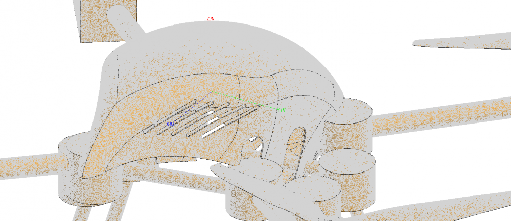
<?xml version="1.0" encoding="UTF-8"?>drone.PNG
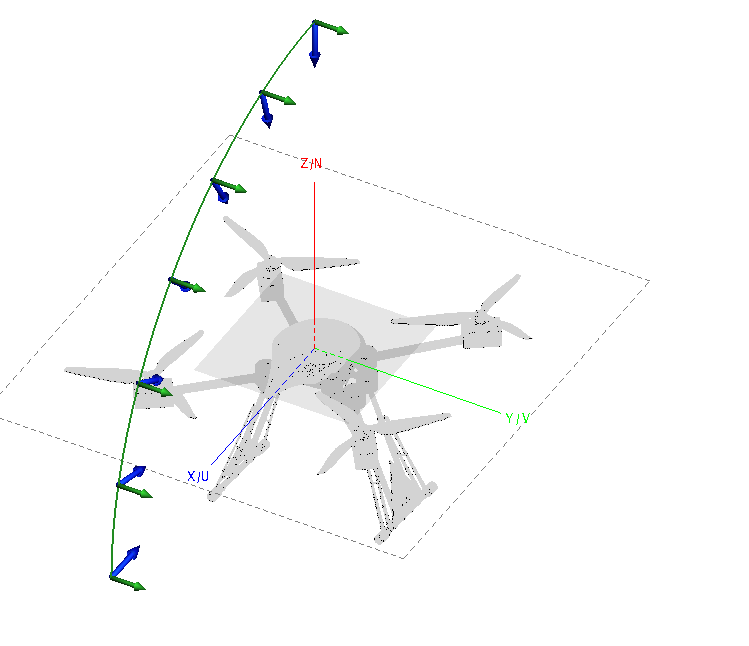
<?xml version="1.0" encoding="UTF-8"?>Drn_mesh.PNG

Tagged:

Answers

  • JIF
    JIF
    Altair Employee
    edited July 2017

    The error means that the MLFMM did not convert. The MLFMM uses an iterative solution method and thus convergence can become a problem in some cases.


    The first thing I would try is to enable 'Activate additional stabilisation for the MLFMM' on the Solver Settings dialog. This is not active by default since it results (usually) in slightly slower convergence, but it has a better chance of reaching a solution for models with convergence problems. Please activate it and let me know if that resolved the convergence problem.


    It looks like you have multiple plane waves. If you are doing RCS studies, you may find the comment listed below useful.


  • Altair Forum User
    Altair Forum User
    Altair Employee
    edited July 2017

    I noticed that your model seems to have a finite thickness.  You can reduce resource requirements quite a bit by removing some of the model complexity (i.e. by deleting the faces 'inside' the drone).  Another option you can try for such high frequencies is one of the asymptotic techniques (e.g. Large Element PO, PO, UTD, etc.).  They won't be as accurate as MLFMM but should get you pretty close with fewer resources.

  • Altair Forum User
    Altair Forum User
    Altair Employee
    edited July 2017


    i.e. by deleting the faces 'inside' the drone

    I tried deleting necessary faces but still i am getting error. Geometry is not stitched properly. CADFEKO transform tools are unable to stitch to form a region.

  • Altair Forum User
    Altair Forum User
    Altair Employee
    edited July 2017

    Please activate it and let me know if that resolved the convergence problem.

    I activated MLFMM stabilization but it didn't worked.

  • Altair Forum User
    Altair Forum User
    Altair Employee
    edited July 2017

    Geometry takes too long to simulate. First, i want to make sure that model is correct for simulation.
    If i simulated different parts of drone, i get the convergence error but my simulation does not stop in between.

    But if i simulate whole drone, the simulation stops in between with the convergence error. (here,i suppose that error % is too large with whole drone).
    Then i did error estimation of drone at one angle. I got to know that geometry consist of lot of error (lot of green, orange triangles).

    How can i use this error estimation solution to refine mesh?


  • JIF
    JIF
    Altair Employee
    edited July 2017


    I tried deleting necessary faces but still i am getting error. Geometry is not stitched properly. CADFEKO transform tools are unable to stitch to form a region.

    I don't think Andries was suggesting that you delete the faces and then set it to dielectric. I think he assumed that part needs to remain PEC and thus you can remove one side (or mid-surface in HyperMesh).


    I noticed that the model has small details, that should not affect the results, but will affect the simulation performance and could lead to convergence issues for MLFMM.


    My suggestion is still that you spend the time to correct / improve the model in CADFEKO. I don't know what parts need to be dielectric and what needs to be metal, maiking it difficult so show you an example. Pick selection of faces that form a single part and union them together. Use the connectivity display to see where there are holes and fill the holes. You should also remove small details that won't impact the simulation results. Once you have one part sorted out, move to the next one until the entire model is fixed.