Hi,
I am using hypermesh to generate CFD tetramesh and boundary layer to model a flow into pipes. I am first working on a simple pipe with an inlet and an outlet. I am using the cfd tetra mesh panel to generate the boundary layer and the tetramesh core.
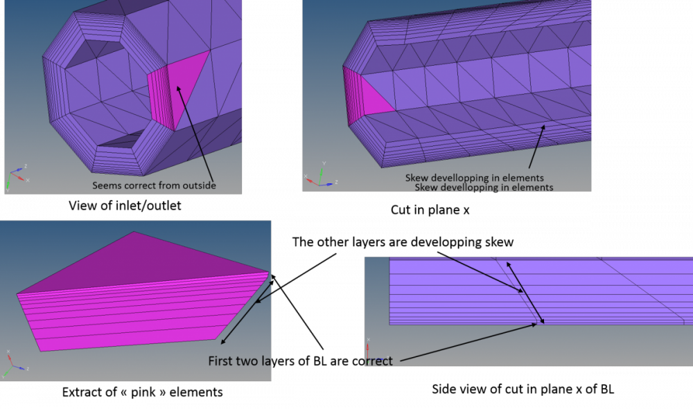
The boundary layer obtained is good for the first couple layers but the elements start to skew at some point which result in a very bad boundary layer mesh. This is extremely disappointing since this is one of the simplest case I can think of. I am planning to use the cfd mesher for a much complex piping case and this kind of mesh is not acceptable. Please help me with this issue. I used hypermesh 12.0.117.
I attached a screenshot of the parameters used for the boundary layer. I also tried several other combination of the parameters. I also tried selecting float or fixed boundary layer without success. I also attached screenshots of the resulting elements to illustrate the problem. I also attach a .txt file containing the model of the pipe. (just change de extension to .fem and import it in hypermesh, I had to change extension otherwise the upload was not authorized). The pipe and inlet/outlet components are used as 2d input mesh for the boundary layer mesh generation.
Thanks in advance for your help, I really need to make this work!
<?xml version="1.0" encoding="UTF-8"?>
<?xml version="1.0" encoding="UTF-8"?>
Unable to find an attachment - read this blog