Optimizing a spanner/wrench in hyper mesh-optistruct
Hi,
I am a new user to Hypermesh, I am wondering if it is possible to optimize a spanner/wrench in hypermesh software (optistruct) and what would the constraints look like or how to apply one (normally there are no constraints acting on a spanner). I have attached the file along with this post.
Any valuable feedback would be welcome.
thanks
Find more posts tagged with
- Geom>autocleanup
- F11 (quick edit geometry) for manual defeaturing used toggle edge, replace point and add/remove point
- Geom>solid edit>trim with lines>with bounding lines for partitioning
- Tools>scale>uniform
- F12 (automesh)>QI optimize>trias + meshing criteria
- 3D>tetramesh>Tetra mesh>Float trias/quads to tetra mesh
- F2 delete the shell elements on solid faces (use mask panel or browser to isolate only 2D elements)
- F10 check elements>3D
- inspect how the mesh conforms to geometry. Use shift+F7 to project nodes to geometry
- shift+F11 to organize elements into design/non-design components
- 1D>rigids to create rigid spiders
- constrain master node of a rigid spider on one end with Analysis>constraints
- define load on master node of a rigid spider on the other end with Analysis>forces in a separate load collector
- reference appropriately the two load collectors under SPC and load in Loadstep definition
- you can find various functionalities with ctrl+f then type in the keyword(upper right corner)
- F1 or H for help while working in any panel
Hi,
I tried optimizing but i am getting an error
*** ERROR # 2150 ***
Invalid Volume or Mass Constraint.
The response type is the total VOLUME.
the upper bound value = 2.6100e+006
the total volume = 8.7003e+006
the design volume = 5.1900e+006
the total mass = 6.5252e-002
the design mass = 3.8925e-002
The design material fraction (percent) should be at least 3 times
the DOPTPRM MINDENS (default 0.01).
Could someone help me solve this error.
<?xml version="1.0" encoding="UTF-8"?>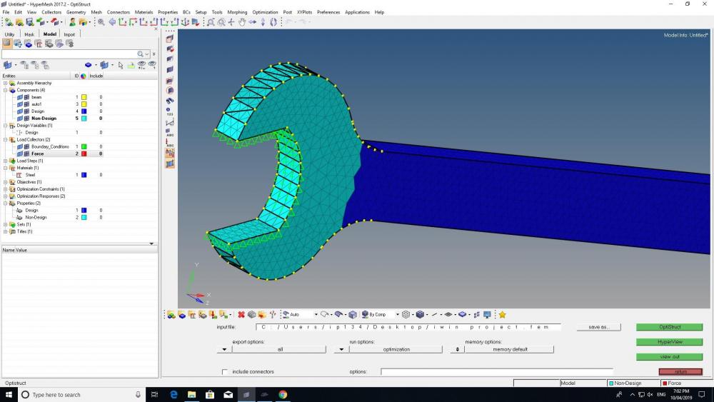
Hi,
this error is due to an invalid total volume constraint.
the upper bound value = 2.6100e+006
the total volume = 8.7003e+006
the design volume = 5.1900e+006
The non-design volume is 3.513e+006, which is more than the upper bound value of 2.6100e+006, resulting in a negative volume of -0.903e+006 available for optimization.
Using mass or volume fraction will ensure valid positive mass/volume formulation.
The model you have shared had some issues. I have remeshed the part and scaled it to 1/10th the size, which I think is more consistent with the loading and material units.
Hi Ivan
Thanks for the help. Would it be possible if you can share the steps you used for future reference.
kind Regards
Hi Ivan
I guess the file 'spanner2_edit.hm' file has not been attached since i cant download it.
Hi,
glad to help. The steps are:
Geometry:
Meshing:
Load step:
Hi Ivan
Is there any other way i could contact you directly if I need any help
Kind regards Iwin
I prefer the open forum so others can benefit from it.
But if there is something that can only be discussed privately you can contact me through email
Thanks, I am completely new to this software and probably may need a lot of guidance from you./emoticons/default_biggrin.png' srcset='/emoticons/biggrin@2x.png 2x' title=':D' width='20' />
You're welcome. There are some great learning materials from Altair university- Practical Aspects of Finite Element Simulation is a good starting point.
https://altairuniversity.com/free-ebooks-2/
Check the following Youtube channels:
Altair University
Altair India Student Contest
ELEATION By Apoorv Bapat
how did you edit the volume of the model by using scale (1/10th) depending on load and force.
Could you provide the steps and whether this has to be done at the very beginning or later stage.
Thanks
by using Tool>Scale>uniform
Tips:
1/10th scale was arbitrarily chosen. Make sure to scale according to your data. Note the model units consistency is N, mm, tonne, MPa.
Scaling can be done at any stages, but it is a good practice to get the geometry right from the start to avoid confusion.
Hi Ivan
I created another model and tried to run but when i run i still get the same error. (all units are in N, mm, tonne, MPa.)
*** ERROR # 2150 ***
Invalid Volume or Mass Constraint.
The response type is the total VOLUME.
the upper bound value = 3.6295e+004
the total volume = 1.2098e+005
the design volume = 8.6894e+004
the total mass = 9.0737e-004
the design mass = 6.5171e-004
The design material fraction (percent) should be at least 3 times
the DOPTPRM MINDENS (default 0.01).
So I did calculate manually Non-Design Value = the total volume - the design volume
= 1.2098e+005 - 8.6894e+004 = 34086 which is less than the the upper bound value = 3.6295e+004.
Formulation for volume fraction:
Volume fraction = (total volume at current iteration – initial non-design volume)/initial design volume
I took 30% of volume as upper bound
Volume fraction = (3.6295e+004 - 34086)/1.2098e+005 = 0.01825
Could you correct me if i am wrong in my calculation with an example and point out where I had made the mistake and if such mistake occurs in the future how to resolve the issue.
I have attached the model along with this file. Kindly let me know if I have done any other mistakes.
please note this is what I considered
moment = 50000n/mm
length = 240mm
force = moment/length
force = 208N
Kind Iwin Philip
Even though the volume available for optimization is positive, it is still below
The design material fraction (percent) should be at least 3 times the DOPTPRM MINDENS (default 0.01).
MINDENS= Sets a lower limit on the amount of material that can be assigned to any design element. Extremely low values for this parameter can result in an ill-conditioned stiffness matrix.
(upper bound volume - non-design volume) / design volume > 3 x MINDENS
(3.6295e+004 - 34086) / 8.6894e+004 = 0.025 < 0.03
Slightly increasing the upper bound volume or decreasing the MINDENS parameter (analysis>optimization>opticontrol) should work.
Hi Ivan
Thanks I will try it out and let you know and any other error in the model and optimization you found out. Plus does the .fem file open in hyper works.
Solver deck (.fem file) can be imported by File>import>solver deck
Hi Ivan,
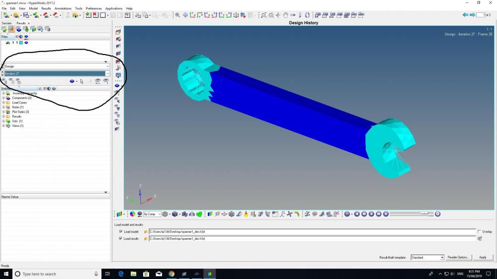
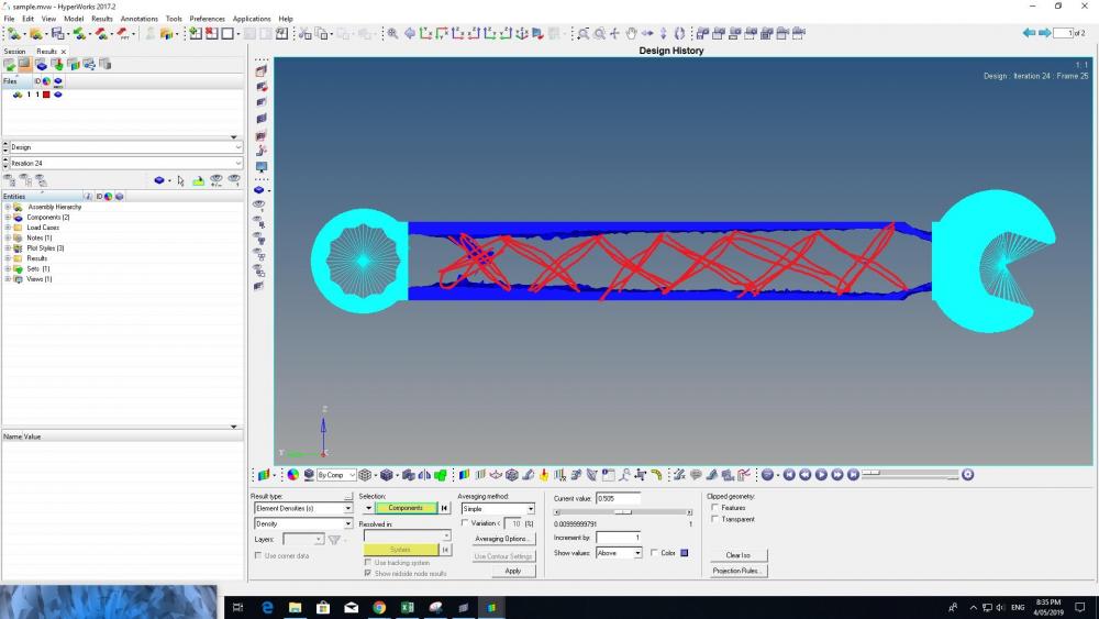
Thanks, Now I understood how the volume optimization works. I tried out and i get the result all the parameters have been satisfied but when I look at the iterations its all the same. I have attached a photo of it and also the file named 'spanner1'. Could you let me know why i don't get an optimized model.
Hi,
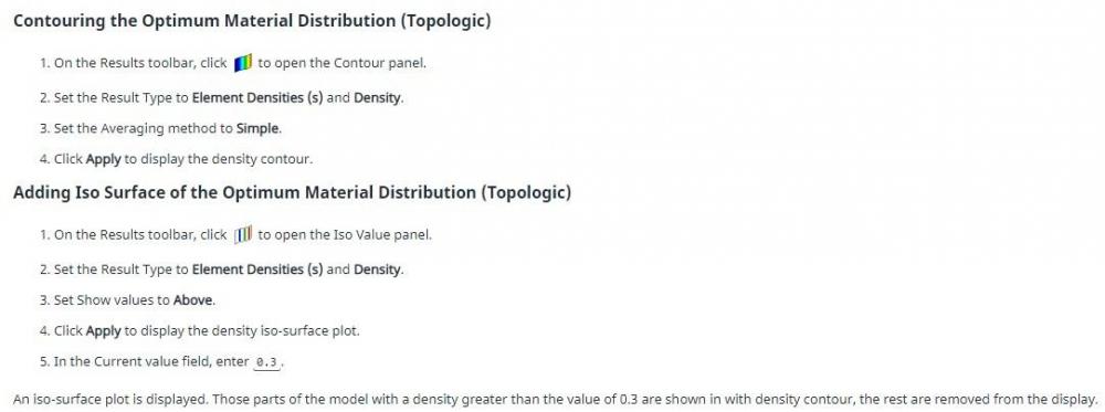
here is how to post-process topology optimization results:
Hi,
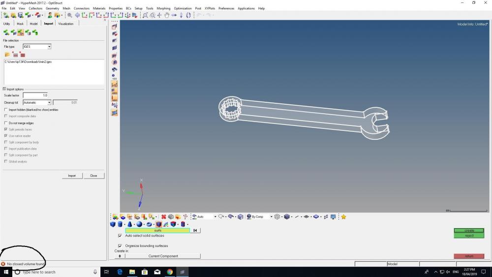
I do have a doubt why does it show ' No closed volume found ' even though i checked everything and all lines are intact.
Solid>Bounding Surfaces cannot be executed, because the solid is already created.
Verify by going to Geom>solid edit panel and picking the solid. Also when in edit geometry mode (for example in the F11 quick edit panel) surface edges of solid objects are slightly thicker than surface edges not enclosing solid objects.
Hi,
Thanks for that. Could you please help me out with how to do FEM analysis for this model. (the steps involved in this process)
Kind Regards
Iwin Philip
Like mentioned before, I suggest you start with Free eBook: Practical Aspects of Finite Element Simulation (a Study Guide)
Check these Youtube channels:
Altair University
Altair India Student Contest
ELEATION By Apoorv Bapat
These tutorials might help:
https://altairuniversity.com/learning-library/linear-static-analysis-tutorial-of-a-bracket/
https://connect.altair.com/CP/SA/training/self_paced/os_linear/content/linear_1/PDF/1a_doit.pdf
https://altairuniversity.com/wp-content/uploads/2012/05/Tutorial_BasicFEA_AcademicBlog.pdf
First try to do it yourself and ask for help if you fail.
Thanks a lot . I will have a look. But i did try out many forces and other possibilities but still not getting a model like what i wanted to as shown in the picture. the only result i am getting is the model without the red lines which i think is wrong. any valuable feedback/suggestions appreciated.
Kind Regards
I am not at my HyperWorkstation so I will look into your model later in the weekend.
I tried applying force close to the edges as shown in the figure both the sides and got a result. This is the closest i got to. I am trying to get the x design in the middle.
In the model you shared the tetramesh is too coarse in the interior of design component (see image below). Because topology optimization results are mesh dependant there is not enough mesh resolution available for truss-like structure. I have remeshed the model with hexa/penta mesh with uniform element size through the thickness.
To get truss-like structure minimum member size control (mindim) should be used. From Free eBook: Practical Aspects of Structural Optimization (A Study Guide):
Controls the smallest dimension to be retained in topology design, as well as minimizing the checker board effect caused by
the mesh and giving a more discrete design. Since the optimization is seeking a discrete value of 1 or 0 for the elements, this
constraint usually improves the clarity of the design, by penalizing intermediate elements that would otherwise form.
Although minimum member size (MINDIM) control penalizes the formation of small members, results that contain members
significantly under the prescribed minimum member size can still be obtained. This is because a small member in the structure
can be very important to the load transmission and may not be removed by penalization. Minimum member size control
functions more as a quality control than a quantity control.
It is recommended that MINDIM be at least 3 times, and no greater than 12 times, the average element size. The average
element size for 2D elements is calculated as the average of the square root of the area of the elements, and for 3D elements,
as the average of the cubic root of the volume of the elements
Because the model has uniform depth it can be simplified to 2D for learning purposes. Try out different optimization controls before moving to 3D.
Try the following options on topology optimization card (DTPL):
-parameters: mindim
-pattern grouping: one plane symmetry
-extrusion
-draw
<?xml version="1.0" encoding="UTF-8"?>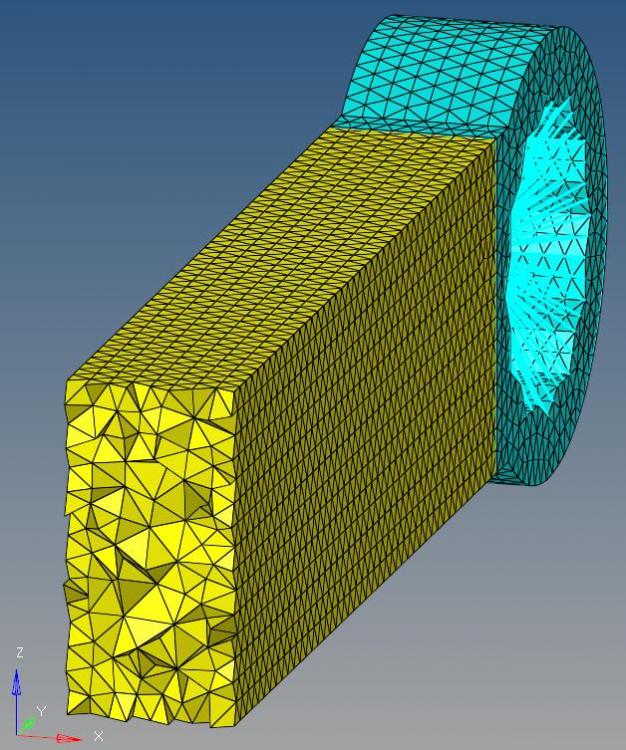
<?xml version="1.0" encoding="UTF-8"?>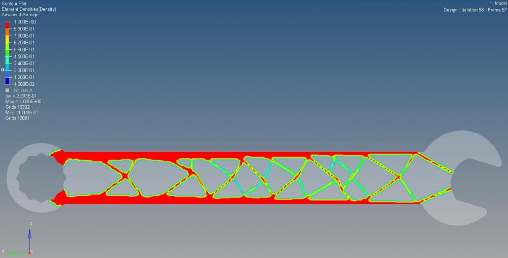
<?xml version="1.0" encoding="UTF-8"?>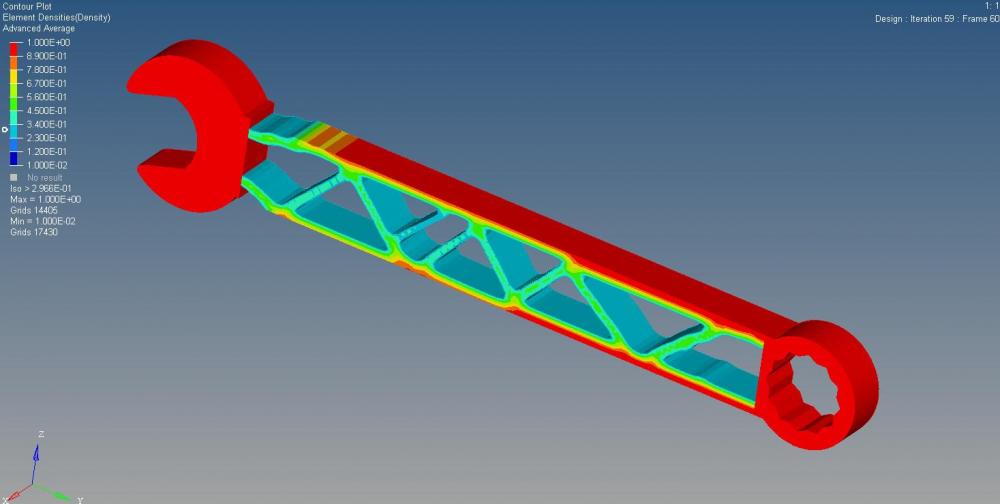
Thanks
Just to get some point clear
1) For hexa meshing -> 3D -> Solid Map -> one volume -> source shel -> quads only -> elem size= 1. I have attached a snap shot below
2) as you mentioned 'recommended that MINDIM be at least 3 times, and no greater than 12 times, the average element size' so if element size is 1 then for 3D models should it be 3 (MINDIM).
3) when I increase my element size to 2 i get an error message saying
' Element # 17725, element type HEXA.
*** PROGRAM STOPPED: ERRORS DURING ELEMENT QUALITY CHECK.'
I usually first create the 2D mesh on surfaces, then use 3D>Solid Map>general. This procedure gives better control over mesh quality. Meshing complex geometry with quads only option might result in bad mesh quality.
The error you have is due to bad element quality. You should remesh or bypass element check (not recommended) with control cards> PARAM> CHECKEL>NO
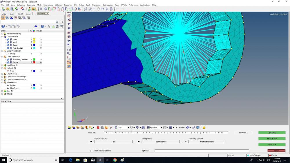
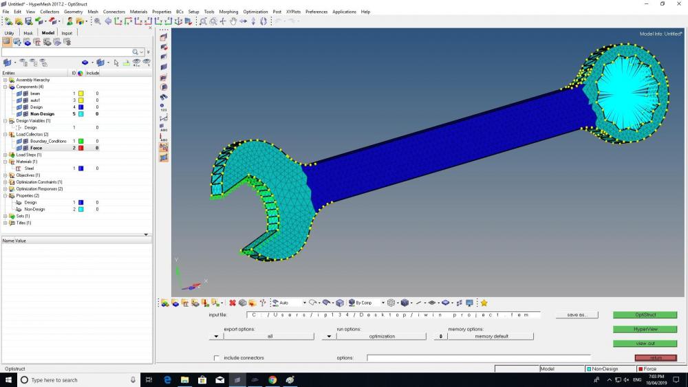
Can you help with this what this light blue color indicates and i get a mesh value of 0.01. i am using element optimize method.




Hi iwinphilip
It depends on the type of optimization you need to perform. For optimization you need to organize the geometry in to design and non-design space. The non-design space resembles the constraining area where no design changes takes place.
Have a look at the e-book about Optimization in which it is explained in detail. ( https://altairuniversity.com/free-ebooks-2/free-ebook-practical-aspects-of-structural-optimization-a-study-guide/)
Also refer OptiStruct online help where you will get tutorials on optimization.