shell-solid elements constraint

Altair Forum User
Altair Forum User
Altair Employee
edited October 2020 in Community Q&A

Hello,


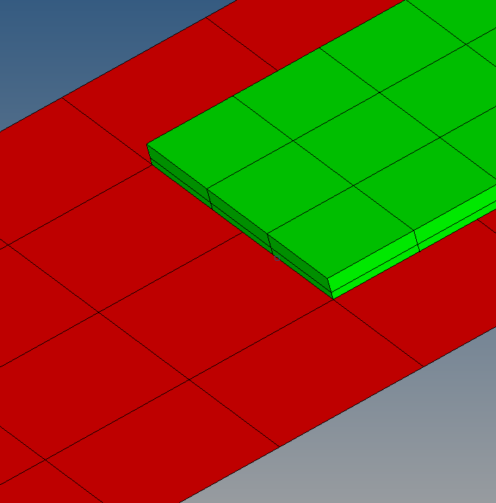
I am trying to simplify my model by modelling a zone with solid elements and the rest of the part with shell elements, but I got a problem on how create a tied constrain between shell-solid elements so that the deplacement and rotation could be transmitted correctly from the shell to the solid elements so that the result should not present any difference from the 'plate' model where all the elements are shell.


Do you have any idea how we make this contraint successfully?


Thank you very much in advance!


<?xml version="1.0" encoding="UTF-8"?>Capture.PNG
<?xml version="1.0" encoding="UTF-8"?>Capture2.PNG

Tagged:

Answers

  • Rahul Rajan_21763
    Rahul Rajan_21763 New Altair Community Member
    edited May 2016

    you can connect elements via rigids.From first screenshot i see element density is also not same for 2d & 3d.

  • Altair Forum User
    Altair Forum User
    Altair Employee
    edited May 2016

    you can connect elements via rigids.From first screenshot i see element density is also not same for 2d & 3d.

    First, thank you for your reply.

    And yes the problem is that the mesh elements size is not the same and the nodes between shell-solid elements does not match !!

  • Rahul Rajan_21763
    Rahul Rajan_21763 New Altair Community Member
    edited November 2020

    With remesh you can achieve same mesh density & put shell layer inside solid concept without using rigids.Refer pdf from practical finite element analysis book.

    Unable to find an attachment - read this blog

  • Altair Forum User
    Altair Forum User
    Altair Employee
    edited May 2016

    you can connect elements via rigids.From first screenshot i see element density is also not same for 2d & 3d.

    And after that which constraints/contacts cards should I add between the brick and the shell layer inside ?

  • Rahul Rajan_21763
    Rahul Rajan_21763 New Altair Community Member
    edited May 2016

    If you want to define contact then rigid elements are not needed & contact would based on type of solver.So here it would be edge to surface contact.

    Which FEA solver you are using & what type of analsyis you want to run?

  • Altair Forum User
    Altair Forum User
    Altair Employee
    edited May 2016

    If you want to define contact then rigid elements are not needed & contact would based on type of solver.So here it would be edge to surface contact.

    Which FEA solver you are using & what type of analsyis you want to run?


    Thanks for the reply,

    I am using LS-DYNA for crash simulation.

  • Rahul Rajan_21763
    Rahul Rajan_21763 New Altair Community Member
    edited May 2016

    Then define contact interface which support edge to surface contact in LS-DYNA.

  • Altair Forum User
    Altair Forum User
    Altair Employee
    edited October 2017

    image.png.3b4d364d96c19a401e6253b9ad4c50af.pngHow  to do it i seen this in above pdf or 

    image.png.4c81844b8bb134e126278b3fe4763e10.png

    It will not create penetration or intersection problem ?

  • Rahul Rajan_21763
    Rahul Rajan_21763 New Altair Community Member
    edited November 2020

    If objective is to do simple linear static analysis then above method is fine.For explicit analysis penetration and intersection check is important.So there connection with beam or rigid element is more suitable.(I believe we have shared multiple information for this question wrt to Radioss solver)


    So inserting one layer inside solid element or having coating of shell element at junction would be file. PFA .fem file for Optistruct solver for both cases.

    Unable to find an attachment - read this blog

  • Altair Forum User
    Altair Forum User
    Altair Employee
    edited October 2017

    It mean these technique are not workable in radioss ?