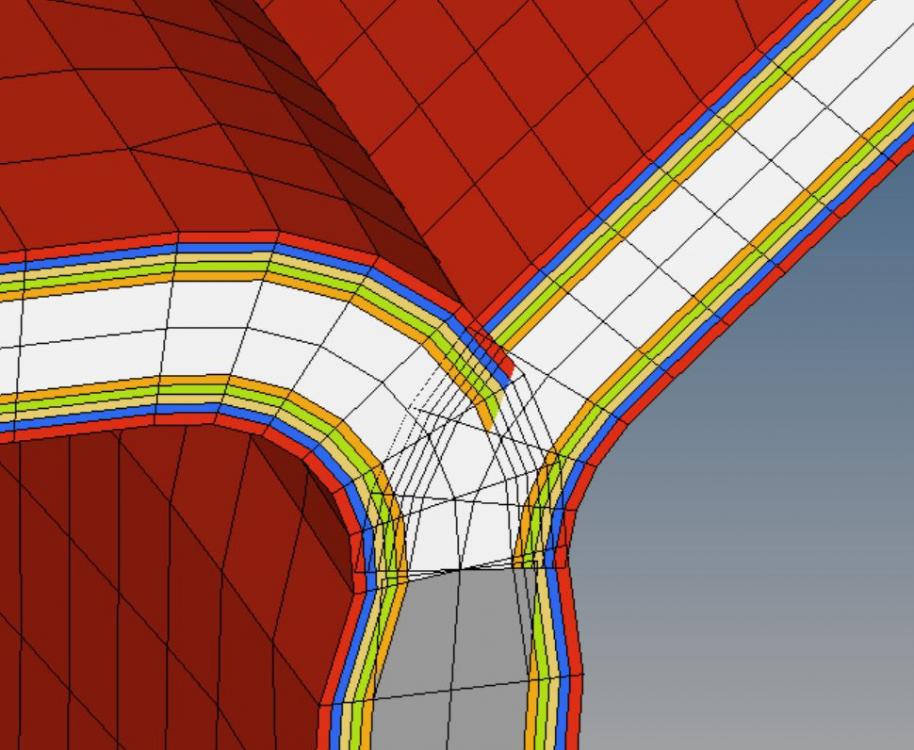
T-junction composite

Altair Forum User
Altair Forum User
Altair Employee
edited October 2020 in Community Q&A

Hi all,


the part is going to be a composite part therefore I imported a middelsurfaced model.

As I'm working with HyperMesh for the first time, my first goal was to get to know the software and creating a lay-up so I did some tutorials as well especially those for composites. Now I have tricky problem as it is not simple shape that I want to simulate.


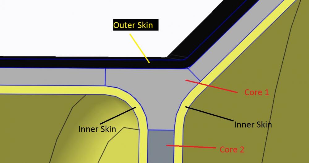
My problem is a T-junction, the lay-up ist not symetric due to that. The outer skin shall go over the junction and is sperated by a core from the two inner skins (picture 1).

How can I set up an area like this in general? How can I manage to get a skin over the junction, how can I avoid overlapping cores that come together? How to handle more complex shapes of cores that are not easily symmetric?


My current solution is shown in picture 2: smear core, overlapping cores and skins that cut though those - quite ugly.


Maybe the middlesurfaced model is the wrong appoach?


I really appreciate your help ;D


<?xml version="1.0" encoding="UTF-8"?>pic 1; t-junction_cad.JPG
<?xml version="1.0" encoding="UTF-8"?>picture 2.JPG

Tagged:

Answers

  • Rahul Rajan_21763
    Rahul Rajan_21763 New Altair Community Member
    edited December 2015

    Hi,

    Please check this post for similar query.


    Regards

    Rahul R

  • Altair Forum User
    Altair Forum User
    Altair Employee
    edited December 2015

    Thank you for your quick answer.

    I already found the post before, unfortunately they did not get a problem solving answer.

    I tried to use sublaminate and interface laminate, but yet, I don't understand how the interface laminate function woks.


    That topic seems to be interesting to some others, someone who alredey managed to make a junction would be helpful.


  • Altair Forum User
    Altair Forum User
    Altair Employee
    edited December 2015

    Hi jo08lyxe,


    Do you want the entire set up as a single laminate?


    Instead, why not have three laminates one on the top, two inner skins?


    If you want to have a single laminate with sublaminates, then you should insert interfaces.

  • Altair Forum User
    Altair Forum User
    Altair Employee
    edited November 2020

    I am attaching a example model I made for a T junction mesh

    Unable to find an attachment - read this blog

  • Altair Forum User
    Altair Forum User
    Altair Employee
    edited December 2015

    Can you explain me the order of the definitions of interfaces?

    When I move definitions of interfaces up and down, plies change their position sometimes, and sometimes they don't.


    INT 1 -> Top left1 -> Left1

    INT 2 -> Top Right -> Right1

    INT 3 -> Left1 -> Right 1


    I couldnt't explain a logical realtionship between changing INT 1 with INT 2 or why you name in INT 1 Top left 1 first and Left 1 second?


  • Altair Forum User
    Altair Forum User
    Altair Employee
    edited December 2015

    Hi,


    My observation is this all changes with the direction of element normals.


    So If Element normal is in Z direction and Top left1 should come before Left1. That is why in the interface I had topleft1 first and left1 the next.

  • Altair Forum User
    Altair Forum User
    Altair Employee
    edited December 2015

    Thanks for your hints, I managed to adapt my model to yours and made good progress.

    I still have a problem that I don't understand.

    As you can see in the picture, I my plies are layed correctly and the analysis runs without an error message. I have four sublaminates (green = right; pink = left; white an above = top; gray = middle) and one interface:

    INT 1 left (pink) -> middle (gray)

    INT 2 middle (gray)  -> right (green)

    INT 3 left (pink) -> top (white)

    INT 4 right (green) -> top (white)


    <?xml version="1.0" encoding="UTF-8"?>sim3.thumb.JPG.e6b2c34d3624062e7f141d52a


    As soon as I add plies to my sublaminates right and left, at the moment they consist only of on ply each, the lay-up breaks down. By changing the order of the plies in INT 3 (now top -> left) and INT 4 (top -> right) I get a correct lay-up again. This has probably something to do if the number of plies ist a even number or not.


    <?xml version="1.0" encoding="UTF-8"?>sim2.thumb.JPG.ea1e15cc7d31e3df3eb1d8671


    But when I start the analysis, I get the error 640 concerning stack 5 which is the interface laminate. It is no matter, if I just add one ply to each side, or more.


    'STACK 5 is incorrectly or ambiguously defined. This could be due to disconnected substacks, duplicate interfaces or inconsistent interfaces orientations. Please verify the substacks and interfaces thoroughly.'


    Could the switching of the order of plies in INT 3 and INT 4 be an inconsisten interface orientation? I could also imagine that the second ply on one of the two sublaminates does not 'follow' the first. For example, in the right sublaminate green is set in the interface, the beige coloured ply (next to the green ply). I referred also this the ply lay-up:

    <?xml version="1.0" encoding="UTF-8"?>Unbenannt.thumb.JPG.2122949f19079834f570


    I can also upload my model if necesary.


    P.S  My upper plies above the core (white) meet the lower plies again as the core ends after a while. So there is dirct contact of the upper plies and the lower plies

  • Altair Forum User
    Altair Forum User
    Altair Employee
    edited December 2015

    Hi,


    Sorry for a late reply. Make sure no plies are repeated in different lamiantes/sub laminates.


    If possible please share the model file.

  • Altair Forum User
    Altair Forum User
    Altair Employee
    edited November 2020

    Hi Prakash,

    I could set up my model, now the interface works properly. The mistake was somewhere within the plies that I tried to add.

    For everyone else who is interested, my model is attached.

    I have a last question before we can close this topic.

    Every laminate can have several options (total, membrane, bending, smear, smear core, symmetric....)


    The diffderent types are described at your online help at point 5:

    http://www.altairhyperworks.com/%28S%283fu2zyrlbyi03xcofiue25jd%29%29/hwhelp/Altair/hw11.0/help/hwd/hwd.htm?create_laminate_dialog.htm


    How does the laminate types work with interfaces?

    The function smear core uses the last ply of an ply laminate as core material, for example.

    When you use interfaces they consist of sublaminates which have the laminate option total automatically, the interface laminate type can be changed though.

    Which orders define my cores now? Is the order of the sublaminates desicive? Can I handle two cores in one interface laminate actually? As you can see in my model, I want to use two cores that have to be managed.

    Unable to find an attachment - read this blog

  • Altair Forum User
    Altair Forum User
    Altair Employee
    edited December 2015

    Hi,


    My understanding is that outer circumference ply will act as core for smear core similar to ply laminate.


    In order to use two cores in different sublaminates, try to keep the core ply as the last ply.

  • Altair Forum User
    Altair Forum User
    Altair Employee
    edited September 2016

    Hi,


    I just wanted to say, that I had the same Error 640 in my model. I had to define my Interface as 'STACK', which I didn't do before. Afterwards, I had click 'realize'.


    Kind regards


    Konstantin Heiss

  • Altair Forum User
    Altair Forum User
    Altair Employee
    edited September 2016

    Hi, 


    Can you share your model please?