COMPOSITE MATERIALS

Altair Forum User
Altair Forum User
Altair Employee
edited October 2020 in Community Q&A

Hello there ,


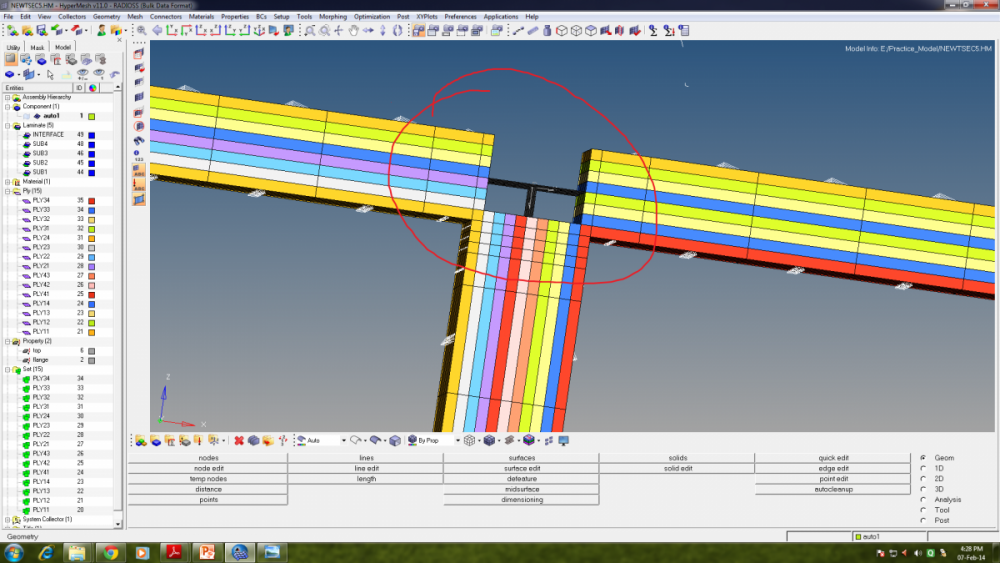
 I am started learning composite modelling in hypermesh for radoiss solver(bulk data). I started with T-section. Everything has been checked(element normals, mat orientation) before i created plies and i created stacking sequence using sublaminate and interface. 


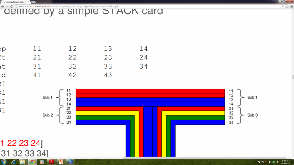
The problem i am facing is i couldn't get the proper T-connection at the center of the T-sec which u can see in the 1st snap and the ideal T-sec should be like the one in the 2nd snap.

I really have no idea of what went wrong.


I need a suggestion!.


regards, chandru<?xml version="1.0" encoding="UTF-8"?>post-29709-0-47711000-1392188201_thumb.p<?xml version="1.0" encoding="UTF-8"?>post-29709-0-25239100-1392188219_thumb.p
Tagged:

Answers

  • Altair Forum User
    Altair Forum User
    Altair Employee
    edited March 2014

    you can try creating a new property for the horizontal elements. select card edit for that new property and assign a value of zero to the  'Z0' field. Make sure to chance the normals of the horizontal elements so they are pointing downward.instead of upward.

  • Altair Forum User
    Altair Forum User
    Altair Employee
    edited July 2014

    I have the same problem tooo.... can anybody help us further ??

  • Altair Forum User
    Altair Forum User
    Altair Employee
    edited July 2014

    It might be a visualization error, the image shown in the training material is clearly not a hypermesh model screenshot. Play a little with the sublaminate stacking order and you'll notice different visual representations (weird!). In my experience this can be very misleading and frustrating at times. Try doing a simple analysis and inspect the results to see how the geometry behaves.

    If it helps, attached are some examples of different models I played with in the past when dealing with this kind of geometry.


    AA: Split the webb into two componentsnotice the purple row of elements at the beggining of the webb.

    BB: Same geometry but different plies. In this example The webb has a core ply which doesn't extend to the flanges.

    CC: Added fillets at the T junction. The checkerboard color of the webb is due to the fact that  I duplicated the webb elements and separated them into left and right webb (trying to create two continuous stacks . 

    DD: same as CC but without the double webb.


    good luck!


    <?xml version="1.0" encoding="UTF-8"?>post-30148-0-75987000-1406244706_thumb.j

    <?xml version="1.0" encoding="UTF-8"?>post-30148-0-43579200-1406244709_thumb.j

    <?xml version="1.0" encoding="UTF-8"?>post-30148-0-51525400-1406244712_thumb.j

    <?xml version="1.0" encoding="UTF-8"?>post-30148-0-49604000-1406244715_thumb.j