Hey there,
I am comparing different ways to simulate a sandwich structure going through a 3 point bending test. In order to check if I am defining well the structure, I have calculated theoretically the maximum stress and compared it to the different simulations I have done. Below are the results of a 3 point bending test applying a total force of 110N on a test-tube of 100x15x10 mm :
Theoretically: Maximum stress- 7.33 MPa
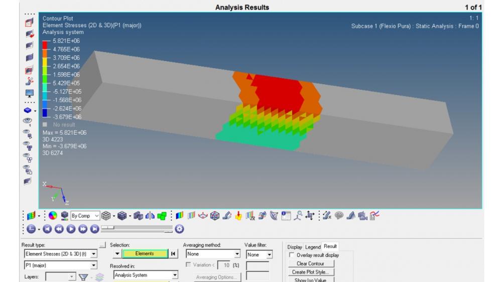
1 solid (3D elements):
<?xml version="1.0" encoding="UTF-8"?>
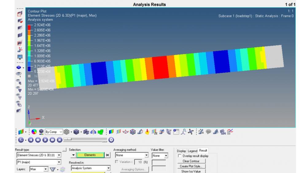
Plies (2D elements)
<?xml version="1.0" encoding="UTF-8"?>
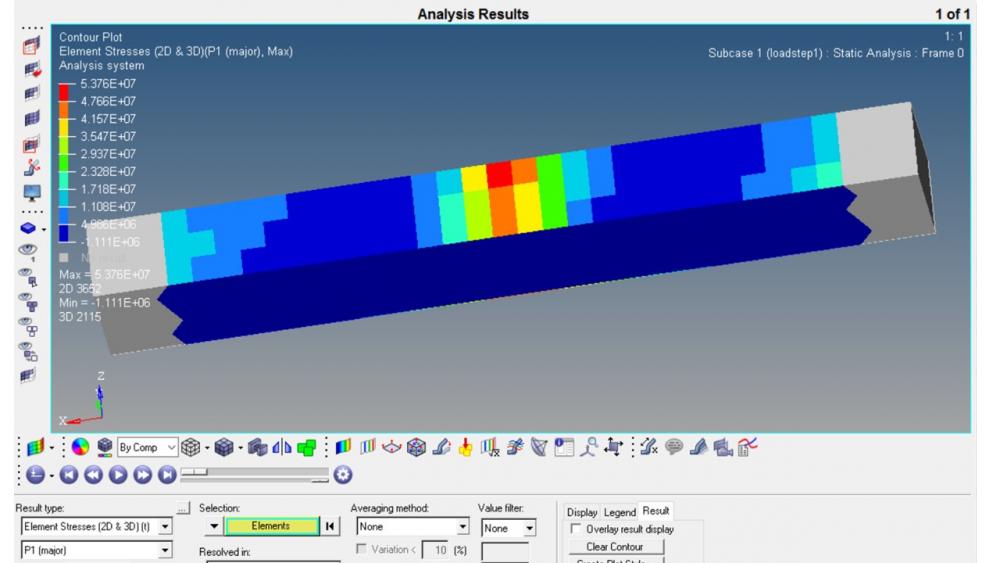
Core (3D) +Plies (2D):
<?xml version="1.0" encoding="UTF-8"?>
The total dimensions of the three test-tubes are the same, as well as the boundary conditions. Therefore, I don't understand why I am obtaining such different stress results nor which would be the best option to simulate this test.
I hope you can help me with my problem.
Thanks in advance!