The Siemens Community Catalyst program was co-created with our community to acknowledge technology leaders who consistently contribute to the Siemens Community. Nominations are accepted on a rolling basis.
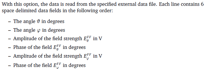
Could someone specify the format for the external ASCII file when loading radiation pattern data into the AR Card in EDITFEKO? I am aware of the documentation but would appreciate a clearer example of the format.
Thankyou
Hello,
Are you running into problems when following the description in the documentation? I can provide an example, but I don't know how a simple example will make it any more clear.
Below is an example file that defines (as indicated in the documentation) the values for Theta, Phi, abs(E_theta), phase(E_theta), abs(E_Phi), phase(E_Phi):
75 0 0 0 1 0 105 0 0 0 1 0 75 140 0 0 1 0 105 140 0 0 1 0
It has only two theta values and two phi values (grid of 4 points). Does this example make it more clear?
Hello, Are you running into problems when following the description in the documentation? I can provide an example, but I don't know how a simple example will make it any more clear. Below is an example file that defines (as indicated in the documentation) the values for Theta, Phi, abs(E_theta), phase(E_theta), abs(E_Phi), phase(E_Phi): 75 0 0 0 1 0 105 0 0 0 1 0 75 140 0 0 1 0 105 140 0 0 1 0 It has only two theta values and two phi values (grid of 4 points). Does this example make it more clear?
Thanks a lot for your help, that makes it much clearer.
I am exporting far field polar data from POSTFEKO. I would like to input this back as ASCII in PREFEKO and get the same radiation pattern result. However the far field data is in terms of gain. The documentation attached states I need Amplitude Field Strength in Volts. Is it possible to get this from the polar data?
<?xml version="1.0" encoding="UTF-8"?>
Hello
Is the data plotted on the Polar graph calculated by FEKO? If so, you can also display other quantities on the polar graph, such as the real or imaginary part of the electric field of a component (theta or phi component). Thus, you should be able to get all the information that you are looking for onto the graph and then export it. I have never tried this and thus my comment is based on what I expect should work.
Is there a reason why you are not exporting an FFE file and using that as a source at the AR card? That should be much easier, but assume that the data that you are trying to export originates from FEKO or at least is a far field DataSet.
If the data that you are looking at does not originate from FEKO and you only have the gain values, then you will have to work that value back to the electric field. If you know what the losses in the model and at the sources were, then you can calculate the directivity and if you then know the power level at the source, you can calculate the magnitudes of the fields. There is no way to calculate the phase. I would try to avoid this route as far as possible.
I have provided some ideas, but without know what you are starting with, it is difficult to guide you. The easiest is if the far field was calculated in FEKO, then use one of the native FEKO formats such as the FFE file or even spherical modes (SPH file) as the source.
Hello Is the data plotted on the Polar graph calculated by FEKO? If so, you can also display other quantities on the polar graph, such as the real or imaginary part of the electric field of a component (theta or phi component). Thus, you should be able to get all the information that you are looking for onto the graph and then export it. I have never tried this and thus my comment is based on what I expect should work. Is there a reason why you are not exporting an FFE file and using that as a source at the AR card? That should be much easier, but assume that the data that you are trying to export originates from FEKO or at least is a far field DataSet. If the data that you are looking at does not originate from FEKO and you only have the gain values, then you will have to work that value back to the electric field. If you know what the losses in the model and at the sources were, then you can calculate the directivity and if you then know the power level at the source, you can calculate the magnitudes of the fields. There is no way to calculate the phase. I would try to avoid this route as far as possible. I have provided some ideas, but without know what you are starting with, it is difficult to guide you. The easiest is if the far field was calculated in FEKO, then use one of the native FEKO formats such as the FFE file or even spherical modes (SPH file) as the source.
Unfortunately antenna manufacturers only seem to provide radiation pattern data in polar form (with gain values). The goal was to somehow import this into FEKO to visualize the antennas EMF in 3D space. The data is in a similar format to FEKOs text export (Theta/Phi values from -180:180 with normalized gain values (so largest gain is 0)).
Does this seem like a lost cause, is the only option to try and work back to the electric field magnitudes? I appreciate your advice.
Join us for a community conversation on how High-Performance Computing (HPC) and Simcenter PSIM work together to meet the increasing demands of modern power electronics simulation. During this one-hour technical session, you'll discover how leveraging HPC can speed up simulations, improve scalability, and empower engineers…
Join us for a community conversation on accelerating your motor simulation workflow with Simcenter Simlab. In this beginner-friendly session, we'll introduce the platform's automated model-building capabilities and show how easy it is to set up your first electric motor analysis. You'll see the basic steps of geometry…
Join us for a Community Conversation where we'll discuss practical approaches to analyzing complex electromagnetic models using hybrid solver techniques. This session will provide a general overview of how different computational methods can be combined within a single simulation to address models containing varied…