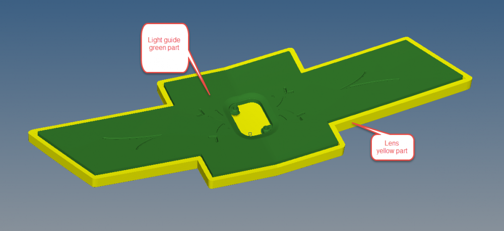
I am supposed to do vibration analysis on the following components. I haven't done this kind of analysis before. I appreciate if you can give me a step by step process for doing this in optistruct
The objective is to Determine during vibration, whether there will be contact anywhere between the lightguide and lens during any vibration loading scenario given below.
- Note, in order to do this analysis, assume vibration is transmitted via the base fixture (to be supplied along with the part data), and then the part will respond to this vibration accordingly.
- Profile shown below, to be repeated 3 times, one for each axis (X, Y, and Z):
1. Frequency = 20 Hz, PSD = 9.9248 (m/s^2)^2/Hz (passenger/ trunk sprung masses)
2. Frequency = 60 Hz, PSD = 3.2313 (m/s^2)^2/Hz (passenger/ trunk sprung masses)
3. Frequency = 120Hz, PSD = 0.1250 (m/s^2)^2/Hz (passenger/ trunk sprung masses)
<?xml version="1.0" encoding="UTF-8"?>