Hi,
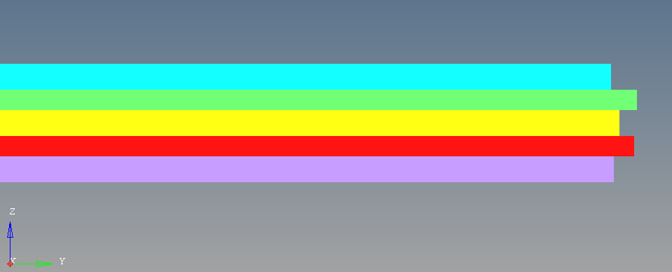
I must model a tensile sample of composite material which consist of 3 layers of aluminium and 2 layers of fiberglass and each layer is linked by an adhesive. My problem is to model interfaces between layers, I have been advised to use gap elements to do it. Thus, on my geometry, even if layers are actually in contact, I let a small distance between them so that when I do my 2D-meshing the software does not consider them as one body and generate common grids between the two. Then I generated gap elements with the 'nodes-elems' option, it creates gaps between the nodes of each mesh and also 1D-elements on 2D-elements I selected. These gaps are stocked in a new component with a PGAP property where I set U0=0.0 (initial gap opening); KA_opts selected option : auto; and MU1_opts selected option : Stick.
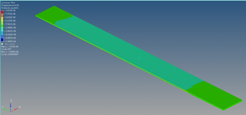
The analysis I want to do is about a tensile test so I fixed one extremity of the sample and I applied a force along y-direction on the other. When I run the solver and observe results on Hyperview, these are not satisfying : it seems that gaps are useless and I obtain the exact same results when I delete them completely, all layers react independently from each other.
As I did my analysis without a huge number of elements, I tried to redefine gaps using the 'node-node' option and link all the nodes with each other, but the results are even worse : there are huge displacement along z-direction (near 30mm with a sample length of 200mm) while the force is along y-direction, plus displacement along x-direction is not consistent either. However gaps seem to keep layers stuck with each other.
Could you tell me if gap elements are really adapted to my case please. And what do I have to do to implement them well.
Thank you