The Siemens Community Catalyst program was co-created with our community to acknowledge technology leaders who consistently contribute to the Siemens Community. Nominations are accepted on a rolling basis.
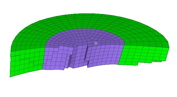
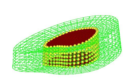
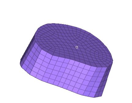
Hi, what are the steps to make a solid mesh inside the doughnut shape solid mesh so that all nodes are matching those of the doughnut please.
Thank you
Unable to find an attachment - read this blog
Use linear solid option by extracting faces of solid elements.See attached video for steps.
Hello.
Thanks but I did not write my question well.
I meant how do you mesh the hole inside
Use spline command to mesh circular region with mesh delete surface ,try to have same mesh on opposite side & use Solid map option to generate hex mesh.
I don't think you can do that with some ... clicks /emoticons/default_smile.png' srcset='/emoticons/smile@2x.png 2x' title=':)' width='20' />
That's doable, but you need some manual works.
I have tried manual but after equivalencing it's still not working
Hi I''ve tried creating one surface mesh on one side and then create a solid map with node path but it's still not working. Any ideas please?
I can't even create two surface mesh and map in between.
Create surface mesh on one side. Make node equivalent.
Project (by copying) surface mesh to another side. Make manual correction to equivalent nodes.
Once you get two surface meshes, you can do 'linear solid'.
Finally, do equivalent again.
Hi Dilen,
You can ruled one side of the hole and position it to other side by using position tool and equivalence it (Manually). And create solid mesh using Linear solid mesh with node path method. I have created and it is working properly. hile equivalencing, make sure that no. of nodes should be equal in both faces where solid elements need in between.
<?xml version="1.0" encoding="UTF-8"?>
Hi Dilen, You can ruled one side of the hole and position it to other side by using position tool and equivalence it (Manually). And create solid mesh using Linear solid mesh with node path method. I have created and it is working properly. hile equivalencing, make sure that no. of nodes should be equal in both faces where solid elements need in between.
Not only 'nodes should be equal in both faces' but also 'element topology should be compatible on both faces.
In other words, even with the same node number, you can not do linear mesh from Quad elements (on 1st face) to Tria elements (on 2nd face)
Hi Any chance I can get a video of the steps please. I tried and still can't get it.
Here's my video:
Thanks very much. One thing is that when I create the mesh on one side the surafce mesh nodes are not near the nodes on the solid mesh. I adjusted the number of nodes but it still does not equivalence in the right way.
Join us for a community conversation on how High-Performance Computing (HPC) and Simcenter PSIM work together to meet the increasing demands of modern power electronics simulation. During this one-hour technical session, you'll discover how leveraging HPC can speed up simulations, improve scalability, and empower engineers…
Join us for a community conversation on accelerating your motor simulation workflow with Simcenter Simlab. In this beginner-friendly session, we'll introduce the platform's automated model-building capabilities and show how easy it is to set up your first electric motor analysis. You'll see the basic steps of geometry…
Join us for a Community Conversation where we'll discuss practical approaches to analyzing complex electromagnetic models using hybrid solver techniques. This session will provide a general overview of how different computational methods can be combined within a single simulation to address models containing varied…