Issues with 3D Meshing

Altair Forum User
Altair Forum User
Altair Employee
edited October 2020 in Community Q&A

Hi,


I realize that this topic may make me seem like a noob with HyperMesh but yes that's pretty much what I am at this point.


I'm trying to use 2D surface meshing and 3D mapping of the mesh on a geometry. 


<?xml version="1.0" encoding="UTF-8"?>ss2.png
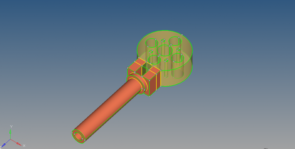
 

I've been able to get fairly far but having issues getting some of the solid parts to become mappable.  


Moreover, there are a lot of shared edges which I can't seem to surpresss (image below) and I'm not sure how to surpress them.  I am hoping to do this to take advantage of hyperworks far superior meshing abilities. 


<?xml version="1.0" encoding="UTF-8"?>ss1.png
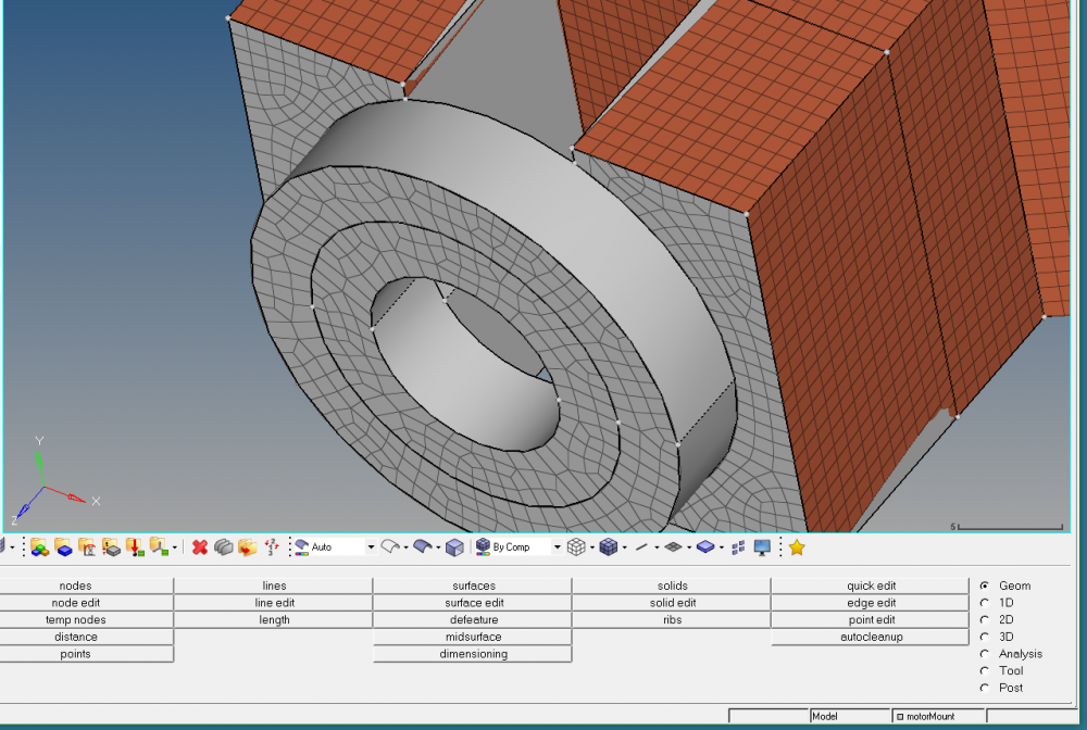
 

My goal is to run a loading analysis followed by topology optimization of the geometry. 


Any help would be appreciated! 


Tagged:

Answers

  • QuyNguyenDai
    QuyNguyenDai Altair Community Member
    edited June 2016

    Maybe share your HM model?

  • Rahul Rajan_21763
    Rahul Rajan_21763 New Altair Community Member
    edited June 2016

    How about 3d tetrameshing?

  • Altair Forum User
    Altair Forum User
    Altair Employee
    edited November 2020

    Attached is the hm file.  


    @Rahul R - I am still getting used to hyperworks but I'll try 3d tetra meshing.  Does this require mappable volumes? 

    Unable to find an attachment - read this blog

  • QuyNguyenDai
    QuyNguyenDai Altair Community Member
    edited June 2016

    At your place, I'll try a 'hybrid' meshing : maximum of Hex and Tet+Penta+Pyramid.

    I used Samcef as FE solver, so this kind of meshing works no problem.

  • Altair Forum User
    Altair Forum User
    Altair Employee
    edited June 2016

    Okay so automeshing works fine, and so does the analysis and optimization (to an extent) on an automeshed geometry. 


    The issue is that when I start splitting up the geometry (as in my original post), and try to add relevant loads and boundary conditions that way, the solver exits with a series of error messages as follows: 


       'CQUAD4      2205       0    4417    4418    4419    4420'     This line was interpreted as:  451331:CQUAD4, 2205, 0, 4417, 4418, 4419, 4420     *** ERROR # 1000 *** in the input data:  Incorrect data in field # 3.   Expected INT > 0 or blank, found  INTEGER (0).


    I am suspecting this error is caused by a property not being assigned to the elements created from solid mapping.   The solid map component collector has the property assigned but I am still getting this error.  


  • tinh
    tinh Altair Community Member
    edited June 2016

    Enter tab 'Mask' on data browser

    click on Isolate column '1' of Elements>2D

    delete all 2D elements because your model is 3D


    Again to mapping the tube with block. If you cannot find mappable solution,

    can we separate the tube from block while meshing? then we will connect them by something like RBE3 / contact ???

  • Altair Forum User
    Altair Forum User
    Altair Employee
    edited June 2016

    I had already separated the tube from the block using solid edit.  I later just deleted the rod because it wasn't really helping the optimization (and I didn't want it removing material from the rod).


    I tried deleting the 2D mesh and hiding the original geometry, but was still having issues getting the properties to 'attach' to the solid-map mesh properly


    I decided to go with an automatically generated tetramesh for now, as I could't get the mapped mesh to work as intended. 


    Currently trying to understand the parameters of the opimization panel as I need them :P.


    Thanks for all the tips!