Orthotrophic composite plate with different heights left and right

Altair Forum User
Altair Forum User
Altair Employee
edited October 2020 in Community Q&A

Hi there,

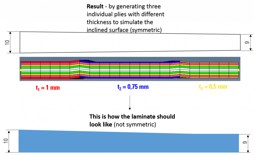
my problem is as followes: i built up a squarish composite plate (carbon) with orthotropic material property. I edited the laminate with 'symmetric' option to realize the orthotropic

material behave. Now my problem is that I want to check the material behave varying ply direction and ply thickness. So the plate should obtain 10 mm height on the left edge and 9 mm on the right edge to simulate an angular load initiation, Now the symmetric laminate option causes a result which I dont want to realize (see attachment). Can you tell me how to realize that? Maybe with shell to solid conversion (how do i get there?)? 

Regards

<?xml version="1.0" encoding="UTF-8"?>laminate.png
Tagged:

Answers

  • Rahul Rajan_21763
    Rahul Rajan_21763 New Altair Community Member
    edited July 2016

    could you share Hm file?

  • Altair Forum User
    Altair Forum User
    Altair Employee
    edited July 2016

    It maybe an issue of visualization.


    I dont think there is an option to give dropoff. Share your model. I will see how I can help you with that.

  • Altair Forum User
    Altair Forum User
    Altair Employee
    edited July 2016

    It maybe an issue of visualization.


    I dont think there is an option to give dropoff. Share your model. I will see how I can help you with that.


    i shared the model in your Dropbox. Thanks alot!

  • Altair Forum User
    Altair Forum User
    Altair Employee
    edited July 2016

    Hi Marioke,


    Please share the file here as I dont have access to dropbox.

  • Altair Forum User
    Altair Forum User
    Altair Employee
    edited November 2020

    Hi Marioke,


    Please share the file here as I dont have access to dropbox.

    Hi Prakash,

    see the attached file.

    Regards

    Unable to find an attachment - read this blog

  • Rahul Rajan_21763
    Rahul Rajan_21763 New Altair Community Member
    edited November 2020
  • Altair Forum User
    Altair Forum User
    Altair Employee
    edited July 2016

    Hi,


    In order to have a smoother visualization, you need to have a smoother transition by dividing the length into several more segments (like 10, 9.9, 9.8, etc...).


    What you have is an averaged approximation.

    Hi,


    that means that I have to define a ply for every 'row' of elements in my plate?

  • Altair Forum User
    Altair Forum User
    Altair Employee
    edited July 2016

    Yes,

    also, plan your modeling. I can see that you have a symmetric laminate. Instead of modeling all plies, you can model half and use symmetric laminate option.

    anyways I think its more a visualization problem.


    Prakash,

    i didn't model all plies, I modeled as you said. Creating 5 plies leads to 10 plies because of symmetric option. But my problem could not be solved by dividing the length 

    of my plies in more segments.