Hi, I'm using LaunchXL-F28069 (Piccolo Series) TI dsp board to develop a inverter. Though it is an inverter my primary application is to used it in rectification mode. To do the synchronization with AC grid I'm trying to use a Phase-lock loop. The tentative control structure is based as follows.
- I read Va, Vb, Vc voltages from grid.
- Convert them into alpha-beta using Clark transformation.
- Transformation was developed using fundamentals. The transformation block in SolidThinking Embed contains only two inputs and it doesn't work in my desing due to imbalance voltage.)
- Alpha-beta convert to DQ0 quantities.
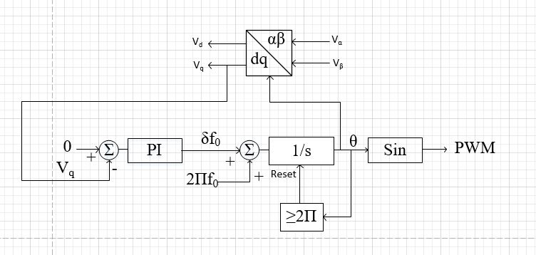
- To do this I used fundamental equations and I manually developed a PLL as shown in the attached file.
- To operate in the rectification mode I need to add an additional phase angle to output theta before generate PWM.
However when I powered the inverter there is a phase fault occurs. (High current flow from input (AC) and no current in output (DC) ). I think the problem is with PLL. I'm looking for a good reference of PLL development. Therefore I would like to seek any help from anyone who developed this kind of setup.
Thanks
<?xml version="1.0" encoding="UTF-8"?>