Time domain result from frequency sweep

Altair Forum User
Altair Forum User
Altair Employee
edited October 2020 in Community Q&A
 こんにちは,

I solved a model in FEKO that consisted of two coils excited by current source of 1uA@60Hz. The idea is let EM waves be produced from symmetric coils, and penetrate inside a spherical body made of both dielectrics, and metal. I got near fields for a single frequency of 60Hz. I intend to simulate an aperiodic time pulse that looks like:
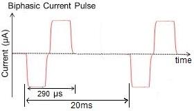
BiphasicCurrentPulse.jpeg.5477788451fe0bb22f6f757e7e8d7b34.jpeg

In Solution frequency dialog box, I put up following values:
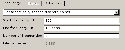
image.png.24a4fe5bfdb80b612c8f3121dfaf7004.png

After solution is obtained, I can create New time signal in POSTFEKO, by specifying values in dialog box below:
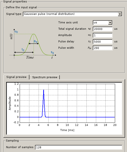
image.png.997620d07fed91a9c0282574cc378910.png

I simulated part of biphasic pulse with a Gaussian pulse. Spectrum preview shows that frequencies should be 0-3.5kHz.
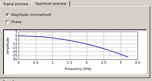
 image.png.a7c490fda84485649821ceae63a28391.png

I specified solution frequency of 500Hz-1MHz, and spectrum preview shows lower frequency of 0kHz. I can't put in start frequency as 0Hz because that becomes DC. 


  1. Is part of biphasic time-domain signal correctly simulated?
  2. Is choice of logarithmicaIly spaced discrete points correct?
  3. Should I change frequency sweep to 0-3.5kHz?


非常感谢你,

FieldForcer

Tagged:

Answers

  • Torben Voigt
    Torben Voigt Altair Community Member
    edited July 2018

    Hi FieldForcer,

    1. Did you get any warnings (I think there should be)?
    2. In general I would recommend to use continuous (interplated) range. FEKO will then catch all the resonces along the frequency range, whereas with discrete frequency points all the information betwwen the calcilated points is neglected.
    3. Of course 0 Hz is impossible. Our recommendation for fmin and fmax for time analysis is
      fmin = 1/sd and fmax = (Nt/sd)/2
      with sd the signal duration and Nt the number of samples.

    There is a video on Youtube about FEKO's time analysis (beginning at ~32:00). It's from 2014, but the basic rules still count: https://www.youtube.com/watch?v=YAruJMWRalI&t=8s


  • Altair Forum User
    Altair Forum User
    Altair Employee
    edited August 2018

    Hi Torben,


    1. Did you get any warnings (I think there should be)?

    Yes, I did get WARNING 594: Due to rounding errors the solution may be totally invalid
                           See also message in the output file Figures8Coil_fr_1_ada_75.out


    I am currently executing time-domain simulation. I will update current thread, once I get result.


    Thanks,

    FieldForcer
     

  • Torben Voigt
    Torben Voigt Altair Community Member
    edited August 2018

    Hi FieldForcer,


    WARNING 594: Due to rounding errors the solution may be totally invalid typically indicates that the model is small compared to the wavelength at the lower end of the frequency range. Using double precision may help.

    image.png.98754e1e6247e2010a119bd8792baa62.png

  • Altair Forum User
    Altair Forum User
    Altair Employee
    edited August 2018

    Hi Torben,


    1. For time-domain simulation, lowest frequency was 100Hz, and higher frequency was 100kHz. When I activated Low frequency stabilization, WARNING 594 disappeared. 


    2. 

    In general I would recommend to use continuous (interpolated) range. FEKO will then catch all the resonances along the frequency range, whereas with discrete frequency points all the information between the calculated points is neglected.


    Continuous(interpolated) range results in frequency sweep for 1000 frequencies, and FEKO gets stuck at 56th frequency. After completion of solution for each frequency, FEKO displayed FINISHED. I was misled that entire simulation completed, but it didn't. When I choose Linearly spaced discrete points with 101 frequencies, FEKO solved the model, and was not stuck at any particular frequency.


    Thanks,

    FieldForcer

  • Altair Forum User
    Altair Forum User
    Altair Employee
    edited August 2018

    In time-domain, when I change Amplitude of pulse to -1, why doesn't FEKO change peak current value to -6A? 


    <?xml version="1.0" encoding="UTF-8"?>DownwardPulse.thumb.jpeg.f0eb3230eb1fd4b985536ea95c52822c.jpeg

  • Torben Voigt
    Torben Voigt Altair Community Member
    edited August 2018

    Hi FieldForcer,


    The direction of the currents in 3D views can be visualized by activating currents. A magnitude as such is always positive.

    <?xml version="1.0" encoding="UTF-8"?>image.thumb.png.f793de63c2167a3d7b7947273570d82e.png


    <?xml version="1.0" encoding="UTF-8"?>image.thumb.png.58708d36ad9fc912d222346292178444.png


  • Altair Forum User
    Altair Forum User
    Altair Employee
    edited August 2018

    Hi Torben,


    Thanks. Continuing from my post earlier, I can define single pulse mathematically. For one of the pulses below,

    BiphasicCurrentPulse.jpeg.5477788451fe0bb22f6f757e7e8d7b34.jpeg

    I can define an upward and downward cosine pulse. For a truncated cosine pulse,

    image.png.829b245842f8789323f4f6551d2f6108.png

    the time-domain function is image.png.594d88de8719306219f2044cf223ffd8.png with W=2.


    FEKO has no problem with following parameters:

    image.png.789bf21006382ba67f778ec2c05dbb3f.png

    This is a continuous cosine pulse. To truncate it with aforementioned function g(t), when I put in symbol pi, and rect(), FEKO throws an error:

     image.png.e09ebd50ebc214aa6f2998b9cf72562b.png 

    I simplified rect() with more general boxcar function. 

    image.png.4ec03e013dae4fd3fc0d15fba361e2d2.png


    How can a truncated cosine be coded correctly?

    Thanks,

    FieldForcer

  • Torben Voigt
    Torben Voigt Altair Community Member
    edited August 2018

    Hi FieldForcer,


    Why not reduce the signal duration itself? One could just use miltiples of 2*Pi for the duration:

    <?xml version="1.0" encoding="UTF-8"?>image.thumb.png.54350b037f6797c9ba4b5920ad3a4028.png<?xml version="1.0" encoding="UTF-8"?>       image.thumb.png.0d3613620a568282a8a7514e0c60042d.png


  • Altair Forum User
    Altair Forum User
    Altair Employee
    edited May 2019

    Hi Torben,

    Thanks for the reply.

    Why not reduce the signal duration itself? 

    Because original signal is a 2 ms, and the pulse is only 290 us. Reducing signal duration is not a design option. Multiplication of time signal with rect window (though a Bartlet window is preferable) can be done, if there is a predefined rect() function in POSTFEKO. 


  • sumithra
    sumithra Altair Community Member
    edited July 2019

    Dear experts,


    Kindly help me out in clarifying my doubts in time domain analysis.

    1. I would like to know procedure to find the  fidelity factor and group delay between 2 uwb antennas.

    2. Type of pulse suited for performing time domain analysis without interfering with notch band.