Load step for quasi static analysis
Hello everybody!
I am new to hyperworks and trying to simulate an autofrettage process (a stempel which is pushed through a tube). What I need is the final state and plastic deformation after the process.
Usually I would create two load collectors for the constraints and loads and then implement a load step (e.g. for a static analysis).
How can I define that the stempel is moving/pushed through the tube instead of an acting force as load definition?
I am also struggling with finding the proper material card for the plastic deformation.
I would really appreciate any help or advice :-)
Cheers
Find more posts tagged with
Thank you for the quick help @Prakash Pagadala!
Somehow I am not able to make it work.
I constrained the tube at one surface in all directions so it can't move (using a load collector with SPC type constraints).
For the stempel I used a different load collector with an SPCD type.
In the final load step I selected the SPC (tube) as SPC and the SPCD (stempel) as load.
It always gives me the following error code:
'An SPCD component must be constrained by an SPC or SPC1 data.'
Maybe you have some further advice on that issue. Would be great!
Thank you very much so far!
Hi @boba_fett
You need to constrain the same node(s) where you have SPCD with SPC in same dof as SPCD.
Hello @Prakash Pagadala
Thanks a lot, I set 300 for dof2 in both the SPC and SPCD and it worked now.
But for some reason the contact analysis doesn't work at all. Usually the stempel has a slightly bigger diameter than the tube which it is moving through. The stempel material is elastic and the tube material is deformable (plastic).
I tried both autocontact via the contact browser and following the tutorial for the bolted flange (2 contact surfaces, an interface with master/slave and the set_elem for both properties) but the stempel and tube don't seem to interact in any way. Hyperworks does the calculation and gives no errors, but seems to act like there are no contact surfaces etc. at all.
Is it impossible to do a contact analysis with a forced displacement of a part?
Hello @Prakash Pagadala
here is my model file /emoticons/default_smile.png' srcset='/emoticons/smile@2x.png 2x' title=':)' width='20' />
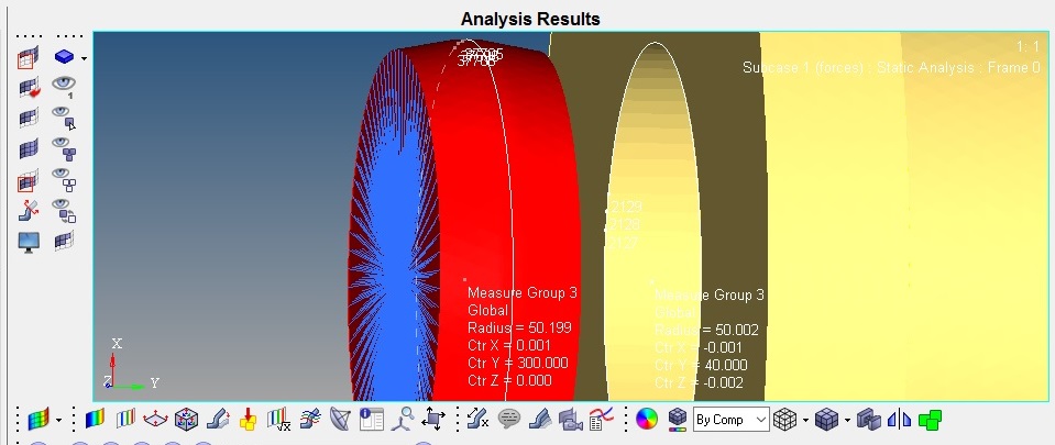
No, it is not. In the middle the diameter of the stempel is 100.40 and the diameter of the tube is 100.
So there should be some kind of contact.
You are right, I was looking at wrong side of the component.
Can you try this model?
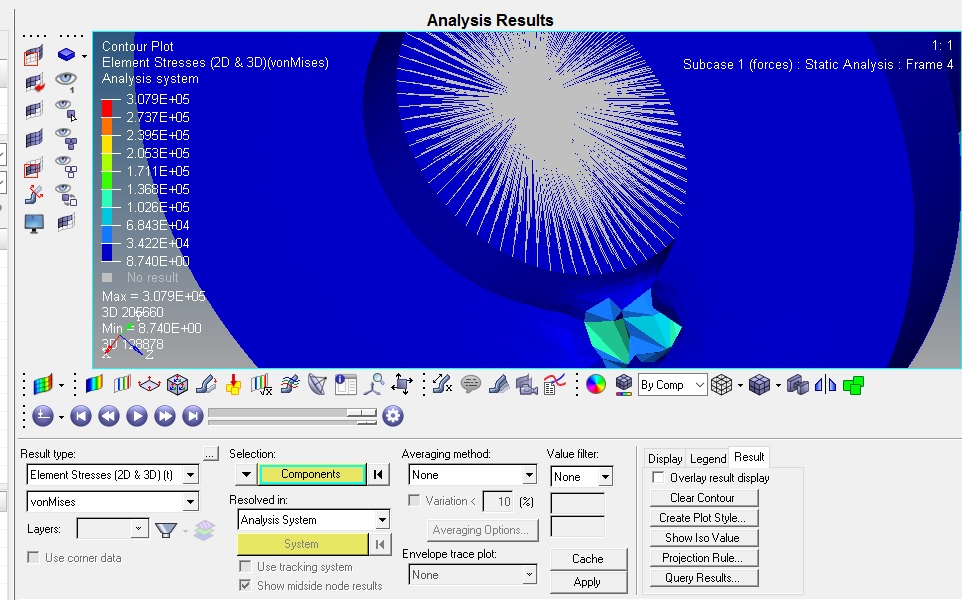
Well... there is some kind of contact now but the results make no sense at all. The geometry as well as the forces and boundary conditions are axially symmetrical but the result is not... and for some reason we only get stresses at the point of contact and not later in the tube as well...
I have noticed that you added an additional set 'Slave' and two cards and that you furthermore changed the interface from stempel to face... why don't we have the interface between the stempel and the tube?
Thanks a lot for your help so far! /emoticons/default_smile.png' srcset='/emoticons/smile@2x.png 2x' title=':)' width='20' />
and for some reason we only get stresses at the point of contact and not later in the tube as well...
Hi Boba,
Can you contour by selecting the elements of the tube because I see element stresses on tube. I think you are looking at contact forces.
I have noticed that you added an additional set 'Slave' and two cards and that you furthermore changed the interface from stempel to face... why don't we have the interface between the stempel and the tube?
Because face comes in contact with inner dia of the tube not the entire Stempel which increases the computation time. I did output contact forces to confirm whether the contact is happening or not. Also I changed the NINC parameter in NLPARM.
The results still don't make any sense in my point of view. How is there no friction and stresses at the inner diameter of the tube? And no stresses at the outer bigger diameter of the stempel? And there are no contact forces as well at the outer diameter of the stempel. In reality the stempel should slide through the tube and stress the whole material inside the tube while the bigger outer diameter of the stempel is stressed and deformed during the permanent contact with friction. Nothing of this is happening in the model/results.
nd no stresses at the outer bigger diameter of the stempel? And there are no contact forces as well at the outer diameter of the stempel.
I see contact forces and stresses on stempel and there are stresses in inner dia. Plot the stress in a range and select the elements in inner dia and you will notice stress.


Hi @boba_fett
You can use either force or enforced displacement as load on stempel but make sure it is not constrained in the direction of motion.