surface current visualisation on dielectric boundaries

Altair Forum User
Altair Forum User
Altair Employee
edited October 2020 in Community Q&A

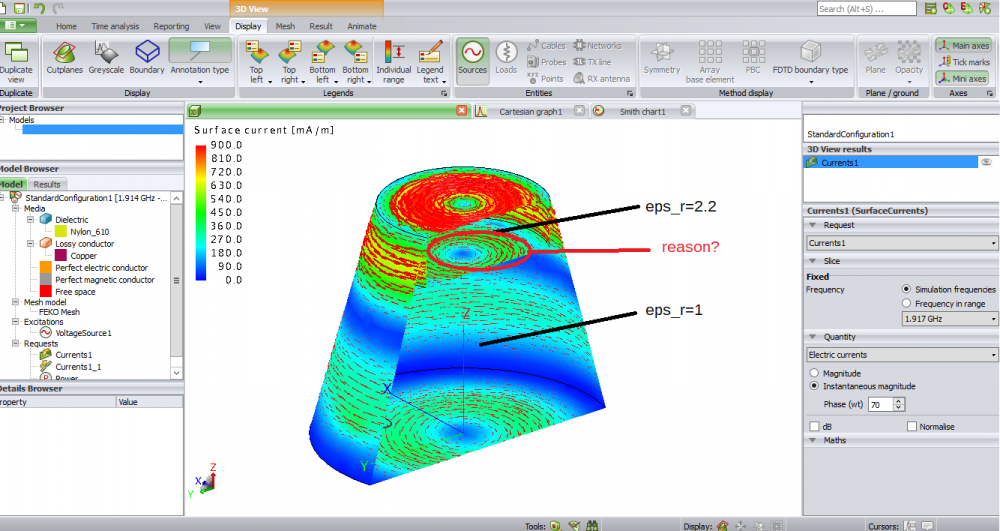
I have noticed that FEKO (SE) shows surface currents at the boundary between different epsilon_r regions.
Could someone explain this effect please?


description in detail:
A dielectric plate is placed inside a conductive cavity resonator. There are two seperate regions inside with different dielectric constant (eps_r=eps_0 & eps_r=2.2). At the resonant frequency of a low order mode the surface current is displayed using postfeko. They are shown at the conductive walls, which is quite clear, but also at the dielectric boundary shell. Why is there a surface current present at this kind of boundery, a dielectric boundery?  Is this some kind of:
1. displacement currens
2. manifestations of the ExH field on the surface at that position and because of the surface mesh at the boundery
3. based on the implementation of the BEM, MoM / boundery conditions
4. somewhat else


Thanks 

<?xml version="1.0" encoding="UTF-8"?>FEKO-dielectric.png
Tagged:

Answers

  • JIF
    JIF
    Altair Employee
    edited October 2017

    Hello scooby,


    Do you mind sending the model? There shouldn't be any electric currents on a dielectric boundary face - unless it is a metal face between two dielectrics. From your description, it sounds like you are trying to model a cone that has conductive outer shell (Copper?) and on the inside there are two dielectrics and at the boundary between the two dieelectrics, there is no conductive face. From your image, my guess is that the model that you created is not what you think you created - thus, you have a metal face between the two dielectrics and that is why FEKO is showing you electric currents.


    Or did I understand your question incorrectly and you know that there is a metal face between the two dielectrics, but would like to understand why the currents are present?

  • Altair Forum User
    Altair Forum User
    Altair Employee
    edited October 2017

    Hi Jif,


    thanks for your answer.

    I don't think the definition of the body is the reason.

    Here are the model definition files:

    Unable to find an attachment - read this blog

  • JIF
    JIF
    Altair Employee
    edited October 2017

    Hello scooby,


    Your model does have a problem.  The problem in your model is that you didn't union the parts. You thus have multiple faces at the same location. We are improving our intersection checks, but it seems the current checks don't detect the intersection.


    I think I now also understand your question. The dielectric boundary is modeled using the SEP (surface equivalence principle) in your example. The SEP introduces equivalent electric and magnetic currents on the surface of the closed dielectric body. I would suggest that you read up on the surface equivalence principle or Huygen's principle. By this principle, a radiating source can be replaced by a fictitious, but equivalent current on a closed surface. These are the currents that you are seeing.


    I hope this helps.

  • Altair Forum User
    Altair Forum User
    Altair Employee
    edited October 2017


    Hello Jif,


    thanks for your explanation. I found the button to visualize magnetic current at the dielectric boundary. Now it makes much more sense.
    After union the components the resonant frequency is a few kHz lower only, this could also caused by the slightly different mesh. I think because of the TE012 field pattern there is no big difference in the final solution.

    <?xml version="1.0" encoding="UTF-8"?>Unbenannt.png