Direction of Total gain in 3D view is disoriented

Altair Forum User
Altair Forum User
Altair Employee
edited October 2020 in Community Q&A

Hello,


I modeled a parabolic dish reflector, and fed excitation with a wire feed at focal depth. I solved the model with MLFMM, and I got following result:

<?xml version="1.0" encoding="UTF-8"?>image.thumb.png.bfd8d37a91243a546cdbe75874b6ac85.png 
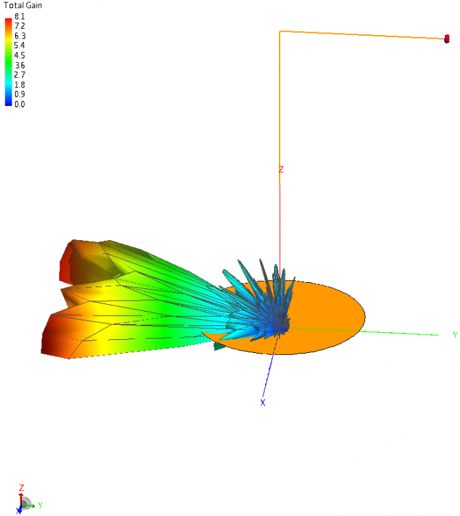
 

The gain of dish antenna is disoriented. How can it be correctly oriented towards reflector?


Thank you,

FieldForcer 

Tagged:

Answers

  • Torben Voigt
    Torben Voigt Altair Community Member
    edited August 2018

    Hi FieldForcer,


    Looks like the radiating element's gain is oriented in the -y direction. From the picture it's hard to figure out. Could you attach the model?

  • Altair Forum User
    Altair Forum User
    Altair Employee
    edited January 2019

    Hi Torben,


    I had done some edits in the file. I have attached that file herewith.


    Thanks,


    FieldForcer

    Unable to find an attachment - read this blog

  • Torben Voigt
    Torben Voigt Altair Community Member
    edited January 2019

    Hi @FieldForcer,


    You defined a voltage source on a wire port at the end of a wire. Normally wire ports are definded either along wires or on connecting points between wires and a metal faces. Defining a wire port on an open end of a wire will probably not result in what you expect. You may for example connect the open end of the port to a metal face like this:


    image.png.d1a7bb4efe9794b13f973c366ced1329.png

    I also saw that you defined a variable 'lambda' with c0/freq. Your global unit is set to mm, so you will have to define 'lambda' like co/freq*1000.


    Still, the pattern of this radiating wire is oriented in the y-direction, so I wonder if you did something wrong?

  • Altair Forum User
    Altair Forum User
    Altair Employee
    edited January 2019

    Thanks a lot for correcting out 'lambda'. There is an alternate instance of wire (lower-right side of figure). Yellow instance is pointing in negative y-direction. I am unsure where that came from, but for sure is causing problem.

    <?xml version="1.0" encoding="UTF-8"?>Orientation.png

    The design conveyed to me does not have wire going through reflecting surface. Can you please upload edited model?

  • Altair Forum User
    Altair Forum User
    Altair Employee
    edited January 2019

    I redefined geometrical parameters, and got some solution.
    ParabolicAntenna.png.682fc474a4c2abaa6498e43ebaa44eda.png


    And later I requested far-field with finer spacing. Though surface currents remain same, but total gain reduces.

     Farfield.png.d2bb6485c06fd34ea5c2c3668f8acdfa.png

    Only difference in above two results is spacing of far-field request. 

  • Torben Voigt
    Torben Voigt Altair Community Member
    edited January 2019

    Hi @FieldForcer,


    The far field request in the second picture sems to have much larger increment than the one in the first picture, although you write 'finer spacing'. I would recommend trying an increment of 1 degree or 0.5 degree.

    Loking at the antenna without the reflector, the main beam is oriented in the negative y direction:

    <?xml version="1.0" encoding="UTF-8"?>image.thumb.png.907d3ec7c0e6ba93f9b31c344fd16e1e.png

    Therefor I would either put the reflector in the negative y-direction or rotate the antenna so that the main beam is in the negative z-drection (where the reflector is now).

    Since your far field request is defined as half space, I assume that you want the main beam of the complete model (antenna + reflector) to be in the positive z-direction, correct?=


    -> If you still have questions, I would ask you to precisely describe what exactly you're trying to achieve with this model.

  • Altair Forum User
    Altair Forum User
    Altair Employee
    edited January 2019

    Hi Torben,


    I tried with suggested increments, and gain increased to 11.25 with same surface current as earlier. Interestingly far-field request spacing has no effect on surface current, and directly impacts only antenna gain.

    image.png.04ee883bf097824c7421fb28b83d764c.png

    Total gain is asymmetrisch. How can it be made symmetric?

    Therefor I would either put the reflector in the negative y-direction or rotate the antenna so that the main beam is in the negative z-drection (where the reflector is now).

    Since your far field request is defined as half space, I assume that you want the main beam of the complete model (antenna + reflector) to be in the positive z-direction, correct?


    Das war ein altes Design, und ich musste es bearbeiten. Ich habe eine neuere Modelldatei angehängt. My guess is feedwire itself may be making total gain asymmetrisch.


    FieldForcer

    Unable to find an attachment - read this blog

  • Torben Voigt
    Torben Voigt Altair Community Member
    edited January 2019

    Hi @FieldForcer,


    I still don't understand the wire structure. Is the wire port at the correct position? In FEKO voltage sources are differential sources where both sides (+ and -) are expected to be connected.

    To get a 100% symmetric field you  will need a symmetric mesh. For this you can use the symmetry options in CADFEKO.

  • Altair Forum User
    Altair Forum User
    Altair Employee
    edited January 2019

    Hi Torben,


    I still don't understand the wire structure. Is the wire port at the correct position? In FEKO voltage sources are differential sources where both sides (+ and -) are expected to be connected.

    I enforced geometric symmetry at z=0 plane. I created a voltage source at end of vertical wire. For simulation purpose, as far as I understood, feed-wire never returns back, and loop never closes. This approach gives me a solution.


    image.png.27273a36727744febee3b598aaaf7d9a.png

    And I tried to mesh model again, and received Error 16222.

    image.png.4a8bb802350c318a92848cd0d2a857ea.png

    Clearly geometric symmetry does not give a solution regardless of location of voltage source on feed-wire. 

    Additionally, mesh size is playing a role here. CEM validates Coarse mesh.

    image.png.0efc04a105750f504fc35dc823ca051d.png

    And with Standard mesh, I get warning.

    image.png.9ead450716761996b39f278f719b2452.png

    What can be done?


    Solution obtained with those warnings has an antenna gain of 9, and surface currents are unmatched with previous results.

    <?xml version="1.0" encoding="UTF-8"?>image.thumb.png.174b684fa6f1ba99199fac2c04e74002.png

    Lobes are pointing in +z-direction, and they are symmetrisch.

    image.png.79a2144674d76062ba42d36b6188e1eb.png

    FieldForcer

  • Torben Voigt
    Torben Voigt Altair Community Member
    edited January 2019

    Hi @FieldForcer,

    The model is not symmetric to z=0, but it is symmetric to x=0:

    image.png.1a2399c22f9879aece2ef8f5d37232dc.png

    Wire segments should be thin. With standard mesh (segment length = lambda/12) the segments are relatively thick. Reducing the rdius would solve this.


    Please note, the Gain values in the 3D view are rounded by default. That's why you seem to get different results for different values of angular increment.


    I still think your feeding (wire port at the end of a wire) is a bit unrealistic.


  • Altair Forum User
    Altair Forum User
    Altair Employee
    edited January 2019

    Hi Torben,


    Wire segments should be thin. With standard mesh (segment length = lambda/12) the segments are relatively thick. Reducing the rdius would solve this.

    That's  a good suggestion. Currently lambda 29.9mm, and segment length = lambda/12  2.5mm. That gives wire radius of 1mm < 2.5mm. CEM Validation works for 0.7mm radius, but not for 0.8mm. What wire radius will be realistic?


    I still think your feeding (wire port at the end of a wire) is a bit unrealistic.

    I do want to make it realistic. I guess you are suggesting that loop should close for current to return back. However I checked back with design given to me, and it doesn't have a path for return current.


    I looked at the result for wire-radius = 0.7mm, and x=0 geometric symmetry.

    <?xml version="1.0" encoding="UTF-8"?>image.thumb.png.622e9a3bbabcf0065fb6851c37d0063d.png


    Lobes indicate that there is minimum total gain along x-axis, and maximum total gain along z-axis. I would expect that when feed-wire is excited, electromagnetic waves travel towards reflector, and as a result, there should have been minimum gain along y-axis.  I am missing out sth crucial. Why don't simulation give zero gain along y-axis? 


    Thanks, 

    FieldForcer

  • Torben Voigt
    Torben Voigt Altair Community Member
    edited January 2019

    Hi @FieldForcer,


    A wire is considered thin if r is roughly smaller than l/4.

    I'm not sure if I understand correctly what 'loop' you are referring to. I only see a folded wire (monopole) with a differential port at one end. Again, the feed is pretty unrealistic, could it be that the one side of the port should be connected to an infinite PEC plane?

    Why do you expect the Gain to be zero in the y-direction?

    Maybe it would be easier if you could just share the design which you are trying to model?

  • Altair Forum User
    Altair Forum User
    Altair Employee
    edited January 2019

    Hi Torben,


    A wire is considered thin if r is roughly smaller than l/4.

    Wires thinner than 0.8mm are not used in antenna design. I can't think of a reason to used 0.25mm wire unless there is a bundle of 8 such wires.  


    I'm not sure if I understand correctly what 'loop' you are referring to. I only see a folded wire (monopole) with a differential port at one end. Again, the feed is pretty unrealistic,

    Loop implies a closed circuit. Antenna examples (ref. FEKO user manual) directly apply voltage source, without closing circuit for feed-wire. I did the same, if that is what you referring to being unrealistic.

    could it be that the one side of the port should be connected to an infinite PEC plane?

    By default, PEC ground plane is created at z=0 only. I can't create a PEC plane at side of the port. This time again CEM validate didn't detect any error. But while execution, job was terminated with ERROR 39138: Invalid specification of an infinite ground plane: geometry not allowed below the plane surface

    I had to shift entire model above z=0 plane, and then I didn't receive any error.

    <?xml version="1.0" encoding="UTF-8"?>image.thumb.png.d781bfdbde645028c62cd6b238151b9e.png

    Addition of PEC plane didn't affect surface current, and gain increased to 10. Still origin of lobes is by default at center of coordinate system, and not center of reflector.  

    Why do you expect the Gain to be zero in the y-direction?

    Antenna can't gain from receiving direction.


    Maybe it would be easier if you could just share the design which you are trying to model?

    Can antenna designer here on Forum, help with realistic design in CADFEKO ?


    Thanks,

    FieldForcer