Defining constraints on a model

Altair Forum User
Altair Forum User
Altair Employee
edited October 2020 in Community Q&A

Dear Sir or Madam,

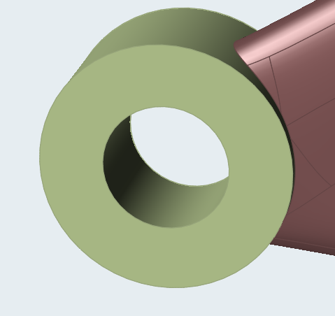
I contact you to get some information and adivces regarding my Inspire model that contains several solid parts:

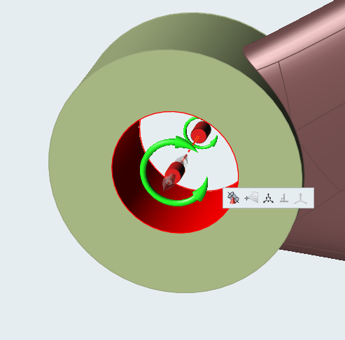
1/ In order to increase the representativeness of my simulations, I would like to configure the connections between different parts by specifying for instance the allowed d.o.f. for a given connection. Is it something  achievable on Inspire ? (Because for the moment, all the parts are -by default- simply 'glued' one to the other according to the initial CAD model)

Otherwise, what are the best way(s) to simulate these connections ? (By using connectors or forces, for instance ?)

2/ For an optimization, is there a way to specifiy directly or undirectly a maximal constraint value for the entire volume (or the design space or at least some specific points) along one direction, or a Von Mises value for instance ? (I am not sure about this but I think it might be possible on HyperMesh and not on Inspire, isn't it ?)

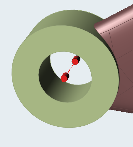
Otherwise, how to take it into account for the optimization constraints? (For the moment I have specified some general displacement constraints at given points but is it possible to better constrain it ?)

Thank you very much in advance for your time and your answers,
Best regards,

Bastien Jamain
Student in Advanced Master at ISAE-Supaéro

Tagged:

Answers

  • Altair Forum User
    Altair Forum User
    Altair Employee
    edited May 2019

    Hi!

    1. You can choose the degrees of freedom allowable for a given connection in a model by creating a support. For instance, if you need a part to rotate freely but not translate, you may apply a cylindrical support on it and double click on it to allow the rotational d.o.f.


    Step 1: Create the part which needs to have free movement in a d.o.f. separately as a 'New Part'

    image.png


    Step 2: Apply a support (this will restrict movement in all d.o.f.)


    image.png


    Step 3: Allow movement in a d.o.f. by double clicking on the support and clicking on the desired free d.o.f arrow such that it becomes green


    image.png


    If you want your parts to not be 'glued' together, you may change their nature of bond from the contacts option into contacting instead of bonding.


    2. You may specify a maximum magnitude for displacement by using the Disps option in the structures ribbon.


    image.png


    Please share your model and ask on this thread for more help.


    Thanks


  • Altair Forum User
    Altair Forum User
    Altair Employee
    edited May 2019

    First, thank you for your answers. I have modified my model and now I have some optimization troubles:


    1/ I would like to perform a topological optimization and apply a load directly on a design-space surface to optimize, so that for instance a force will be split between the remaining elements at each iteration. But are the results meaningful? (I mean, that when I try to do it, I always have a warning message to explain me that some loads are connected to design-spaces and thus that they might be ignored.)


    2/ In this case, is it possible to know if some loads have been ignored during the optimization?


    3/ Does it works better if I use for instance a concentrated mass and rigid connections to the whole design-space to apply the load?


    4/ Otherwise, is it possible to perform this on Inspire or is it necessary to apply loads through non-design spaces only?


    5/ I have run another optimization but I get this error from the result files:


    #--------Generating fresh Mesh
    RUN_STATE = 7 ## Meshing completed successfully
    # Time elapsed - '1511' Seconds <==> Total time taken - '1517' Seconds
    RUN_STATE = 15 ## Realizing model
    #--------Unable to realize contact (Contact 50) as UdbSet for Primary features can not be created
    #--------Unable to realize
    RUN_STATE = 527 ## Synthesis run completed successfully
    # Time elapsed - '68' Seconds <==> Total time taken - '1585' Seconds
    # Error - Unable to ralize synthesis data
    RUN_STATE = 1551 ## Done
    # Time elapsed - '1' Seconds <==> Total time taken - '1586' Seconds
    # --------------------- END -----------------------


    Do you know what might be wrong in my model? Because all my contacts seem correct and bonded to the design space and I was able to perform an analysis of the model but not to optimize it.

  • Simon Križnik
    Simon Križnik Altair Community Member
    edited May 2019
  • Altair Forum User
    Altair Forum User
    Altair Employee
    edited May 2019

    Thank you for the answer, I understand. And in case it is not possible to define a washer because the load would not be applied trough non-design space holes but through a whole surface, do you know if is there is also any tips ?

  • Simon Križnik
    Simon Križnik Altair Community Member
    edited May 2019

    From free eBook: Simulation-Driven Design with Altair Inspire:


    In general, it is best not to apply loads and displacements directly to design spaces, as this often leads to incorrect results. Instead, you should split the part into design and non-design spaces, and apply loads and displacements to the non-design spaces.


    The same applies whether a hole or a flat surface- partition the design space adjacent to the surfaces with loads and BCs and put those volumes into non-design space.