The Siemens Community Catalyst program was co-created with our community to acknowledge technology leaders who consistently contribute to the Siemens Community. Nominations are accepted on a rolling basis.
Hello,
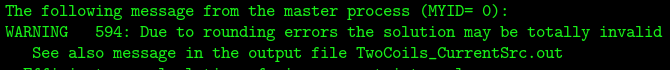
I ran a simulation at 60 Hz with no dielectric, just FreeSpace and PEC material. I get Warning 594.
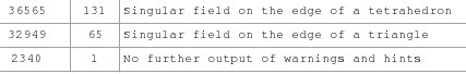
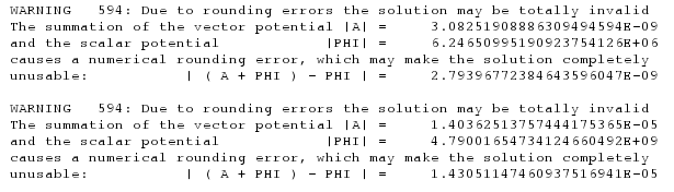
*.out file reports following about warning:
How do I get rid of this warning?
Thanks,
FieldForcer
Hello FieldForce,
The first thing that I would do is to activate low frequency stabilisation. Activating it should get rid of the warning. The *.out file explains quite clearly what the problem is, so no need to explain it further.
Hello JIF,
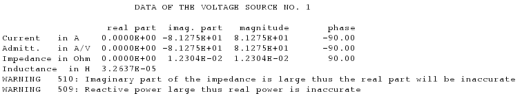
Thank you very much for replying to my post. I activated low frequency stabilization in Solution Settings. And the warning disappeared. Still I have two more warnings 509, and 510 in .out file.
My model has a 1V voltage source at a single port. How do I get rid of these warnings?
When I simulate a current source (large voltage source with large load), solver doesn't give such warnings.
Hi There are two things that you could try:
If that does not work, someone with more low frequency experience should try to help.
Well, based on the error message this is expected. You are increasing the real part and thus the warning is not triggered, but that does not mean the real part of the model input impedance is any more accurate - the point is, the real part is extremely small (not radiating) and the value that is calculated as the real part could be inaccurate (but it will be a very small number). Maybe the real part of the input impedance is not important in your case?
Hi JIF,
Activate double precision
I activated double precision, and it does not fix warnings because warnings 509, and 510 both show up in *.out file.
If the model has a wire loop and the two loop terminations touch vertices of the same triangle, refine the mesh so that this is not the case (I doubt that this is the issue that you have, since FEKO has a test for it).
I used Fine mesh option, and both warnings stick around.
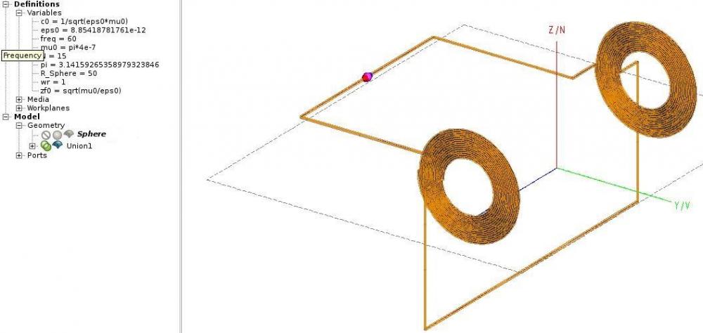
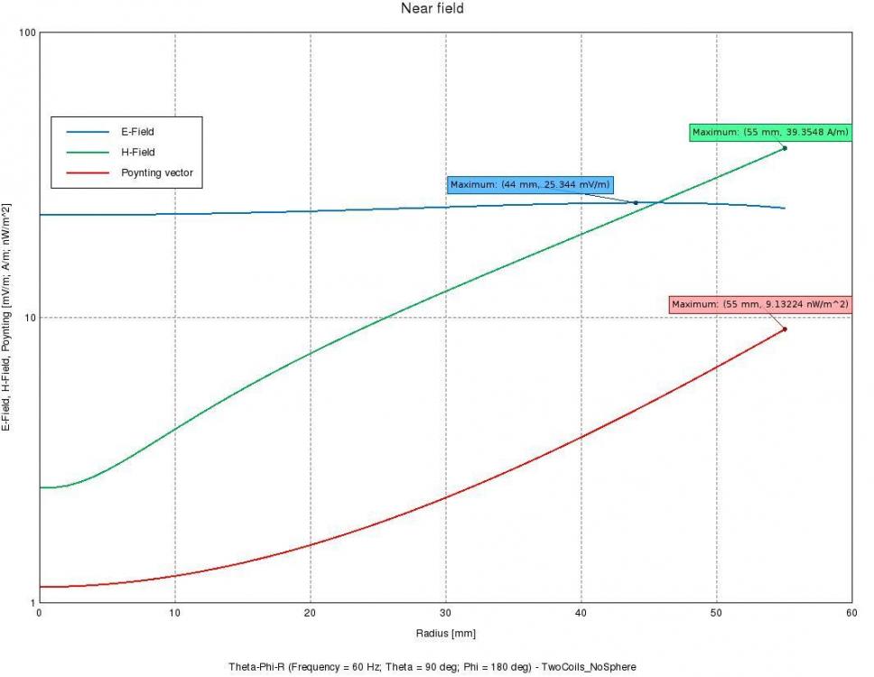
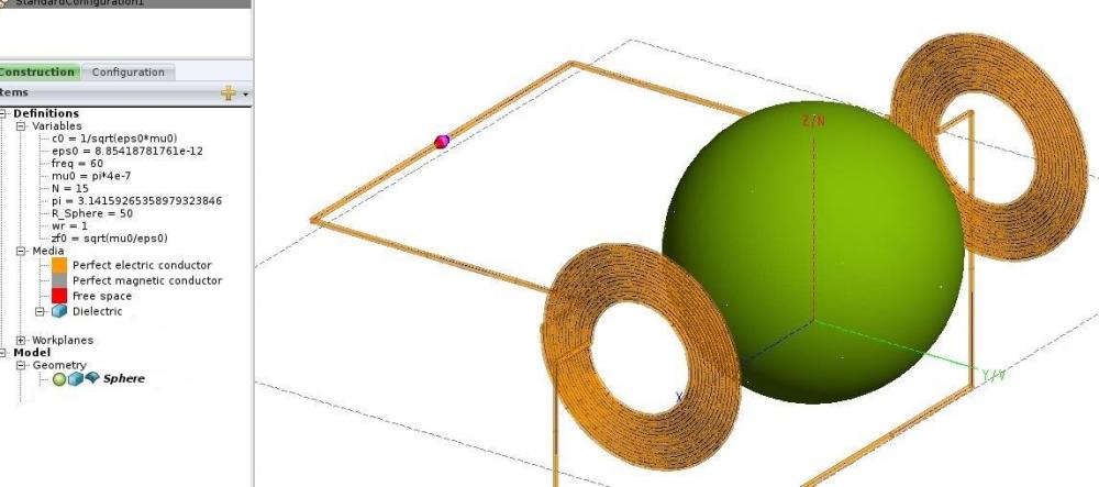
I continued investigating field patterns in my model. I simulated current source in two separate models; first model has two coils and second model has two coils with a sphere. Properties of sphere are free space. Ideally I should get same field patterns, but I get different results.
My model without sphere is:
<?xml version="1.0" encoding="UTF-8"?>
I get following result - X-axis is distance from center of axis across two coils in negative X-direction(negative U-vector),
After inserting a free space sphere, my model is:
I get completely different pattern as well as values.
Shouldn't I expect above results to be exactly identical?
Hi FieldForcer,
For very low frequencies / electrically very small models, the VEP should be much more stable for dielectrics than the SEP (even if the properties are freespace).
Hi Torben,
Sorry for being imprecise: With 'properties are freespace' I meant a dielectric with properties of freespace (eps_r = 1, tand = 0). I was referring to
first model has two coils and second model has two coils with a sphere. Properties of sphere are free space. Ideally I should get same field patterns, but I get different results.
I assumed that you tried to solve the sphere with SEP, so I recommended VEP.
Regarding the Singular field errors, which version of FEKO are you using? In case it's the current version 2018.0.2 I would have to look into it. Is it posiible to attach the model?
Thanks for your reply.
With 'properties are freespace' I meant a dielectric with properties of freespace (eps_r = 1, tand = 0).
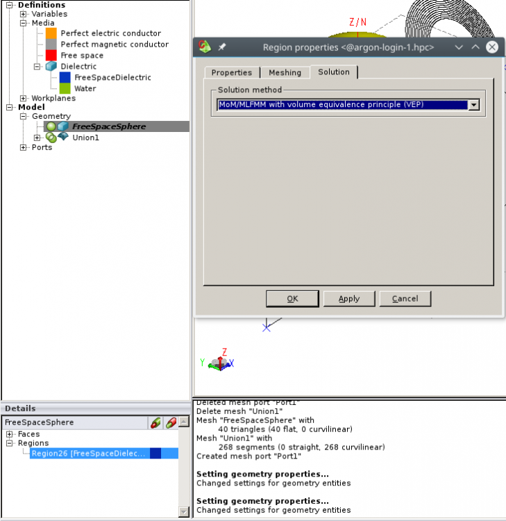
I don't see a difference because eventually they both are free space. Nevertheless, I created a dielectric and assigned it properties of free space with eps_r=1, tand=0.
Solver accepted FreeSpaceDielectric for solution with VEP method. CEM validate detected no error as well.
When I save project files, I see .
Regarding the Singular field errors, which version of FEKO are you using? In case it's the current version 2018.0.2 I would have to look into it.
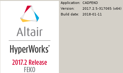
I have 2017 version with Build date in 2018 .
Is it possible to attach the model?
I have attached my model.
Unable to find an attachment - read this blog
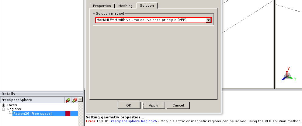
This makes sense. If you want to model free space, not SEP or VEP. So, when there is no dielectric, don't set it to VEP. You are trying to model nothing with something.
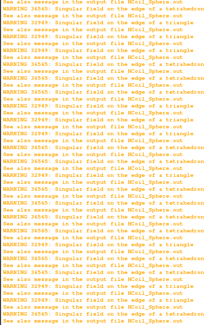
The singular fields are probably due to you requesting points on the surface of a PEC triangle. Either ignore the warning or move the near field request point.
For 100% accurate calculation of near field points we recommend a distance of 1.5 x edge length of the mesh on the surface. This goes for both metallic and dielectric faces.
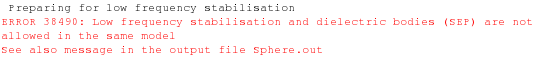
It seems you are suggesting that free space dielectric doesn't need to be set to VEP, and that free space dielectric works well with SEP. However since frequency is low, I had to activate low frequency stabilization that works only when dielectric bodies are set to VEP. For example, if I use dielectric body with SEP and activate low frequency stabilization, Error 38490 pops up.
As I mentioned in 4th reply earlier, these errors do not come when I change properties to water, not with PEC body. It may be at the interface where PEC body meets dielectric body.
...a distance of 1.5 x edge length of the mesh on the surface.
With Fine mesh and VEP enabled, mesh size of spherical region = lambda/12 = c0/(12*freq) = 4.2e5m. Sphere is 50mm in diameter, and I am requesting near fields at distance of 1mm along the radius. Which distance and edge length are you talking about?
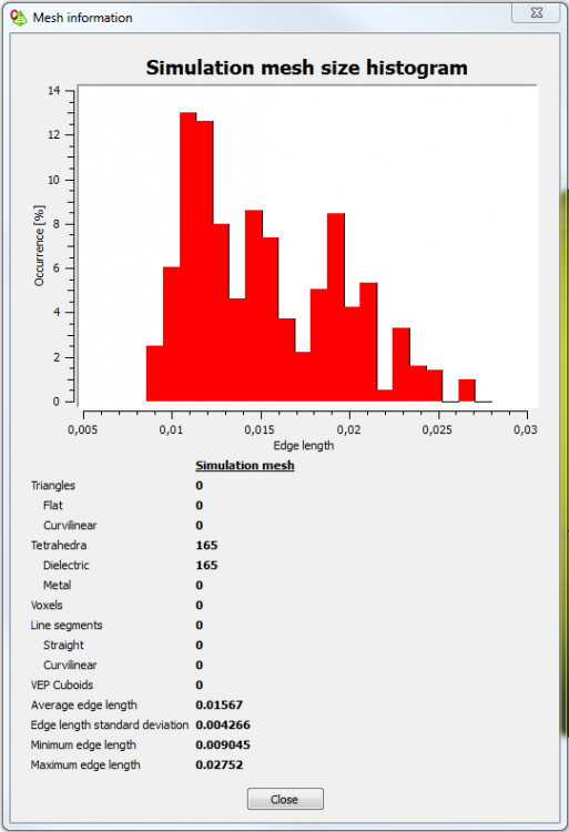
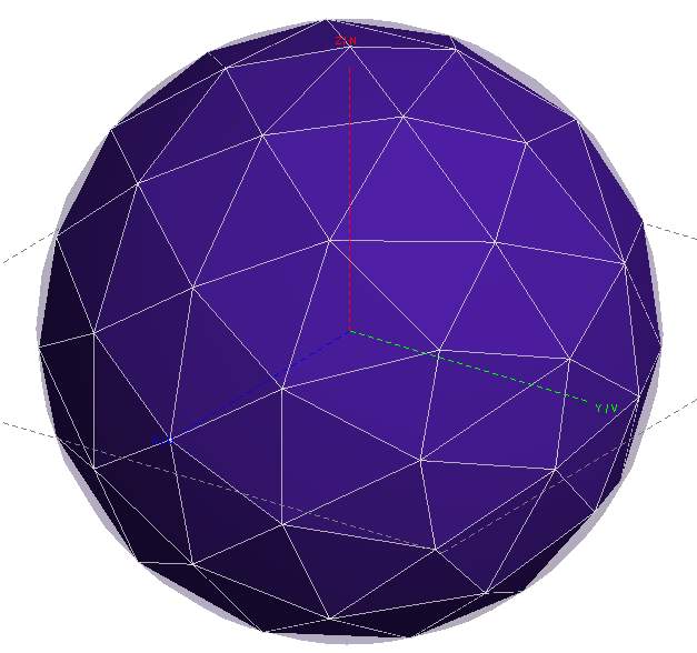
I was referring to the length od the edges of the mesh on a surface. At 60 Hz and standard mesh settings, a sphere with 50 mm diameter will be meshed similar to this:
The edges on the surfaces should be around 1 cm in that case which would in principle allow you to request nar field points 1.5 cm from the surface.
Please note the mesh size of tetrahedra also depends on the dielectric properties of the medium.

.thumb.jpeg.39e40a0796d8f1ad401a499b60be504d.jpeg)