Geometrical Radius and Global Wire Radius
Hello,
My FEKO model consists of two coils placed diametericaly opposite on either sides of hollow sphere.
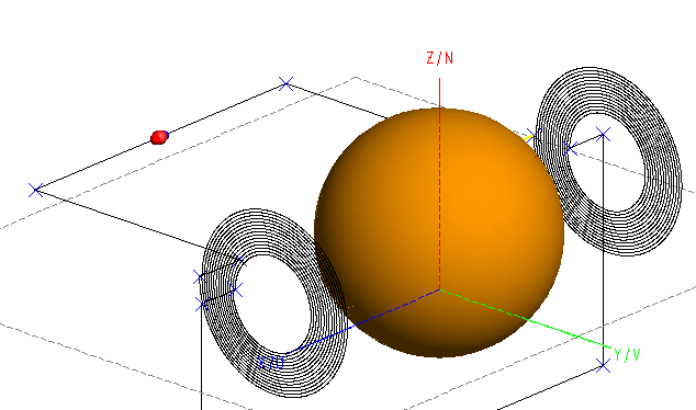
Coils are perfect electrical conductors, and hollow sphere is free space. Excitation is done with 1V 60Hz source.
I have following questions:
1. Often I come across the term, 'Electrical size'. It seems electrical size, geometrical size and mesh size are all related to each other. In this regard,
a. What does FEKO mean by 'Electrical size' of problem?
b. How does 'Electrical size' affect geometrical size and mesh size ?
2. In my model, all wires have radius of 'wr = 1mm'. As shown below, an option in 'Edge properties' could specify 'Local wire radius'.
What is 'Local wire radius', and when is it used?
3. While meshing, there is another option to specify 'Global wire radius'.
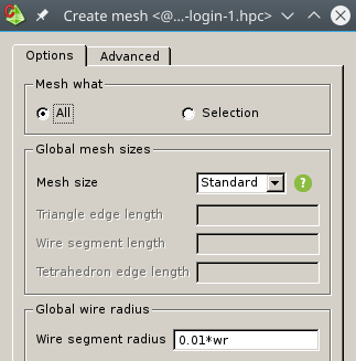
a. How is 'Global wire radius' different from 'Local wire radius'?
b. Since 'Mesh size' is 'Standard', does 'Global wire radius' still affect mesh?
Regards,
FieldForcer
Answers
-
Hello FieldForcer,
Altair Forum User said:Often I come across the term 'Electrical size'. It seems electrical size, geometrical size and mesh size are all related to each other. In this regard,
a. What does FEKO mean by 'Electrical size' of problem?
Electrical size refers to the size of a model in terms of wavelength (usually at the highest or lowest frequency of interest). As an example, a vehicle with dimensions of 3mx1.5m is probably considered quite large, but at 1 MHz (or lower) where the wavelength is 300m, the vehicle is electrically small. That same vehicle at 3 GHz is electrically very big (15 lambda x 30 lambda).
Altair Forum User said:b. How does 'Electrical size' affect geometrical size and mesh size ?
EM engineers often only talk about the electrical size, sine that is what affects meshing the most (in many situations). The required mesh size depends on the solution method, but traditionally the mesh needs to be a fraction of a wavelength and for standard RWG basis function MoM, that woud be a minimum of lambda/10 and smaller for more accurate results. With higher order basis functions, the mesh elements can be increased in size, since they are able to capture more variation within a single element. The geometrical size of mesh elements are important for methods such as RL-GO, where the only meshing requirement is that the geometry be accurately represented by the mesh. It is also important for model where the exact shape or curvature is important (lenses, reflectors, etc.).
Altair Forum User said:What is 'Local wire radius', and when is it used?
It is simply the wire radius setting that is applied locally (on the wire). The local wire radius will always be used, when it has been set. When it is not set, the global wire radius will be used.
Altair Forum User said:3. While meshing, there is another option to specify 'Global wire radius'.
The global wire radius is used when wires don't have a local wire radius set. It makes it easier for the user when the model consists of wires that all (or most) have the same radius.
Altair Forum User said:a. How is 'Global wire radius' different from 'Local wire radius'?
They are exactly the same, but the local wire radius takes precedence when it has been set. Both determine the radius of the wire segments, but only one of them will be applicable for a particular wire.
Altair Forum User said:b. Since 'Mesh size' is 'Standard', does 'Global wire radius' still have affect mesh?
Yes. Remember that the mesh size refers to the edge / segment lengths. The radius is more a model parameter. When you build an antenna, you select a particular wire with a particular radius (model parameter). The meshing on the other hand is a 'simulation parameter' and has nothing to do with the actual (real life) model - it is simply a requirement for the simulation.
I hope this clears up any confusion regarding these parameters.
0 -
Hi JIF,
Thank you very much for your reply. My model has dimensions in mm. For following, Global wire radius = 1mm, and 'Mesh size = Coarse'; based on FEKO User Manual, segment length is 1/8*wavelength.
- At 1GHz, electrical size of model is 3x10^8/10^9 = 0.3m = 300mm. Segment length = 1/8*300mm = 37.5mm. Length of smallest wire is 24mm. After model is meshed, FEKO does not detect any error in CEM validation. I can expect no error because electrical size and model dimensions are comparable. However at high frequencies, all wires act like inductors; not the frequency, I desire to simulate currently.
- At 60Hz, electrical size of model is 3x10^8/60 = 5000000m. Segment length = 1/8*electrical size = 625000m. CEM validation still detects no error in mesh. This surprises me because electrical size and actual dimensions of model are several orders of magnitude apart.
At both the frequencies above, Coarse mesh results in exactly same number of triangles for 'HollowSphere'.
Number of wire segments are slightly different.
Remember that the mesh size refers to the edge / segment lengths.
I interpret that 'edge size = length of wire', and 'segment length is some fraction of wavelength'. Since 'Mesh size' is dependent on wavelength(electrical size), and electrical size is computed based on simulation frequency, wouldn't it be correct to say that 'Mesh size' is dependent on simulation frequency?
Regards,
FieldForcer
0 -
Your comment confuses me quite a bit, but I think it is just the fact that you mixed your terminology. Wires are meshed into segments and each segment has a radius, where the radius is determined by the local or global wire radius setting. Faces are meshed into triangles and a measure of a triangle's size is the edge length (assuming the edges are roughly the same length). In your comment above, you mixed the two (at least it feels that way). The table (extract from manual) is for faces, not wires.
Lets assume that your questions (for now) refer only to the meshing of the sphere (thus, meshing the face into triangles). Your sphere is 50 mm (guessing from the variables that you listed). At 1 GHz, the free space wavelength is roughly 300mm. That means that the electrical size of the sphere is roughly lambda/6. Since the electrical meshing parameters would be lambda/8, I expect that both the electrical and geometrical (curvature) would have an influence on the meshing. For me, a sphere of 50 mm (radius) meshes into 48 triangles at 1 GHz.
The same sphere meshed at 60 Hz (coarse meshing) results in 40 triangles - that is the lower bound for the sphere and the limit is the amount of curvature the meshing needs to take into account.
The same sphere at 10 GHz has an electrical size of (10/6)*lambda = 1.667*lambda in free space. Thus, meshing the face into triangles with edge length of lambda/8 (coarse meshing) should result an many triangles. My test model meshes into 5426 triangles.
Altair Forum User said:I interpret that 'edge size = length of wire', and 'segment length is some fraction of wavelength'. Since 'Mesh size' is dependent on wavelength(electrical size), and electrical size is computed based on simulation frequency, wouldn't it be correct to say that 'Mesh size' is dependent on simulation frequency?
Yes, you are 100% correct and as I have explained above, the mesh size for most solution methods will depend on the simulation frequency (exceptions are RL-GO and UTD).
I don't know what your model is doing differently, but I don't expect more than 7 million triangles for your sphere at the frequencies that you are mentioning and the mesh should differ for coarse meshing for a 50mm sphere at 60 Hz, 1 GHz and 10 GHz.
0 -
Hi JIF,
I am sorry, I didn't mean to confuse you with my comments. I agree wires are meshed into segments. Wouldn't each segment has a length to it? I am taking a cue from FEM. For example, if wire is 10cm long, and # of desired segments = 10, it gives segment length = 1cm for each element.
0 -
Hi
Yes, you are correct. I think my point is that FEKO rarely tries to split the wire (10 cm) into a specified number of segments (10), but rather uses the frequency (and medium around the wire) to determine the wavelength and then meshes the wire into segments that are a fraction of a wavelenth (lambda/12 as an example). Thus, the number of segments is a consequence of trying to mesh a wire into segments of some size. Note that the segment length calculation is independent of the wire (and thus segment) radius. There is a restriction w.r.t. the maximum radius to segment length that is supported due to it using a 'thin line approximation' and if you find that your segments are very 'fat', you should rather model the wires are real cylinders (much more expensive in terms of computational effort).
I hope this clears up everything.
0 -
Hi JIF!
this whole post is for me quite helpful and gives practical insight about modelling of wires.
My problem is the modelling of flat coils made of litz wire (multistrand wire https://en.wikipedia.org/wiki/Litz_wire.). In my model the litz wire of the coils has a diameter of 5 mm, the biggest coil has 20 turns with a outer diameter of approx. 400 mm and the working frequency is 90kHz.
Initially I modelled in FEKO the litz with wires using 'metallic_copper' as medium but I received an error regarding the relation 'maximum radius to segment length' -after meshing there definitely are some small segments that violate the 'thin line approximation'. For this problem you suggest to use 'real cylinders'.
First possibilty: I modelled the litz with hollow cylinders i.e. region=free_space and faces=metallic_copper but I have to input a thickness. What is the correct value to be used as thickness? The litzt diameter of 5mm or the litz radius (2.5mm)?
Second possibility: to model the litz with solid cylinders i.e. region=dielectric_copper. Because in the model I'm using VEP for other material (ferromagnetic) then I 'd have to use VEP also for the litz wires.
Which of the two possibilities is correct for the modelling of litz wires?
Looking forward to your reply!
0