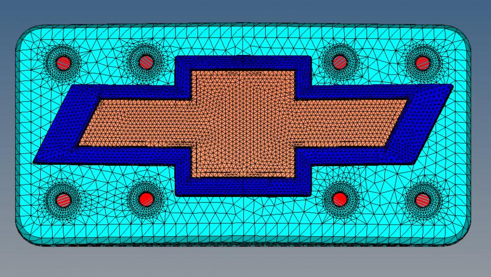
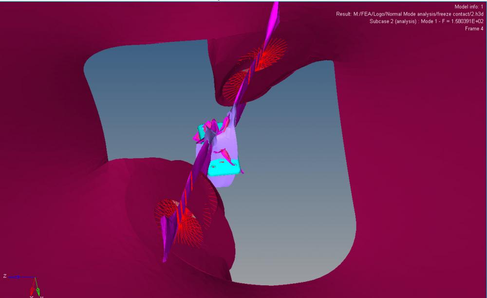
I am doing normal mode analysis of a logo
my problem is that after running the analysis all the components deform excessively. I don't know what is wrong with my model. I appreciate if you can help me
<?xml version="1.0" encoding="UTF-8"?>
First mode
<?xml version="1.0" encoding="UTF-8"?>
********************************************************************
** **
** **
** OptiStruct 13.0.212 **
** **
** Design and Optimization Software **
** from Altair Engineering, Inc. **
** **
** **
** Windows 7 Workstation SP1 (Build 7601) PDS141 **
** 20 CPU: Intel(R) Xeon(R) CPU E5-2687W v3 @ 3.10GHz **
** CPU speed 3100 MHz **
** 114049 MB RAM, 261990 MB swap **
** **
** Build tag: 0760788_5533130_Ce64RBW8UH12M:99179-000 4000000014000 **
************************************************************************
** COPYRIGHT (C) 1996-2015 Altair Engineering, Inc. **
** All Rights Reserved. Copyright notice does not imply publication. **
** Contains trade secrets of Altair Engineering, Inc. **
** Decompilation or disassembly of this software strictly prohibited. **
************************************************************************
*** OptiStruct defaults set from:
install config file: C:\Program Files\Altair\13.0\/hwsolvers/optistruct.cfg.
NOTE # 9199
MSGLMT=STRICT is active, all messages will be printed.
You can suppress some less important warning messages by use of
MSGLMT=BRIEF or UNREF (in config file or in the input data).
1 PARAM(s) were set:
CHECKEL ,NO
*** WARNING 1932: PSOLID ID 4 is not referenced.
*** WARNING 1932: PSOLID ID 7 is not referenced.
*** WARNING 1932: PSOLID ID 8 is not referenced.
*** INFORMATION # 2406
There exist gap/contact elements and linear analysis SUBCASE(s).
For linear SUBCASE, the gap/contact behavior depends on the
initial open/closed status and does not change.
NOTE # 1090
For better node-to-surface contact results with 2nd order solid elements,
you may use PARAM,CONTFEL,YES.
*** WARNING # 2617
CONTACT interface 1 has 5122 Slave nodes that belong to some of
Master segments, indicating likely self-contact condition. This may result in
poor quality of contact elements, redundant contact conditions, and patchy
pressure distribution, especially on curved contact surfaces.
For FREEZE condition this may create an almost rigid surface.
*** WARNING # 2617
CONTACT interface 2 has 5127 Slave nodes that belong to some of
Master segments, indicating likely self-contact condition. This may result in
poor quality of contact elements, redundant contact conditions, and patchy
pressure distribution, especially on curved contact surfaces.
For FREEZE condition this may create an almost rigid surface.
*** WARNING # 2617
CONTACT interface 4 has 18550 Slave nodes that belong to some of
Master segments, indicating likely self-contact condition. This may result in
poor quality of contact elements, redundant contact conditions, and patchy
pressure distribution, especially on curved contact surfaces.
*** WARNING # 2625
CONTACT interface 4 includes areas that have self-contact condition
and apparently pre-penetrations. To avoid detecting false pre-penetrations
(which may appear across thin solids with self-contact on both sides)
declare SRCHDIS smaller than minimum thickness of respective solids.
Or, if it is known that there are no true pre-penetrations in
self-contact areas, use CONTPRM,SFPRPEN,NO.
*** WARNING # 2617
CONTACT interface 6 has 1287 Slave nodes that belong to some of
Master segments, indicating likely self-contact condition. This may result in
poor quality of contact elements, redundant contact conditions, and patchy
pressure distribution, especially on curved contact surfaces.
*** WARNING # 2625
CONTACT interface 6 includes areas that have self-contact condition
and apparently pre-penetrations. To avoid detecting false pre-penetrations
(which may appear across thin solids with self-contact on both sides)
declare SRCHDIS smaller than minimum thickness of respective solids.
Or, if it is known that there are no true pre-penetrations in
self-contact areas, use CONTPRM,SFPRPEN,NO.
*** INFORMATION # 742
The dependent rotational d.o.f. of this rigid element is removed.
RBE2 element id = 2531227
independent grid id = 2701564
a dependent grid id = 10676
This is because there is no need to constrain the rotational d.o.f. of
any of the dependent grids.
*** INFORMATION # 742
The dependent rotational d.o.f. of this rigid element is removed.
RBE2 element id = 2531236
independent grid id = 2701573
a dependent grid id = 99484
*** INFORMATION # 742
The dependent rotational d.o.f. of this rigid element is removed.
RBE2 element id = 2531237
independent grid id = 2701574
a dependent grid id = 99705
*** INFORMATION # 743
The total number of rigid elements, whose rotational dependent d.o.f.
are removed because there is no need to constrain those d.o.f., is 10.
*** WARNING # 6325
STRESS is requested above the first loadcase and there are eigenvalue
loadcases. Stresses will be calculated and output for all eigenvectors.