The Siemens Community Catalyst program was co-created with our community to acknowledge technology leaders who consistently contribute to the Siemens Community. Nominations are accepted on a rolling basis.
Submitted by Joe on Sat, 05/11/2013 - 22:30
Please help me with the following:
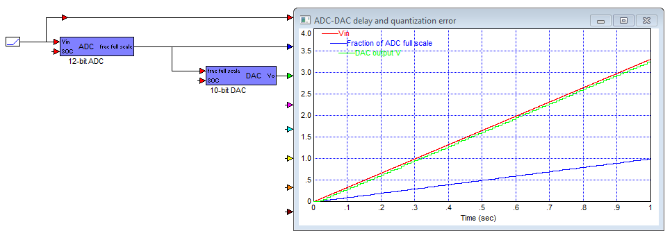
In the ADC-DAC diagram from the Digital Power addon shouldn't I get the same output as input? Here is the plot:
The output is a step when the input is ramp.
Submitted by Anders89 on Sat, 05/11/2013 - 22:53.
The ADC and DAC blocks model the sampling delay and quantization error you get when using these devices. These are important concepts.
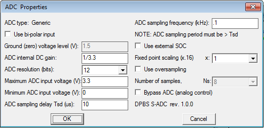
As you can see from your ADC simulation block settings below, your choice of a very slow ADC sample rate (100Hz) will result in large delay and dominates the error and is the primary cause of your steps on the DAC output. The hardware ADC conversion time on a typical C2000 is in the 200 nanosec range, in your dialog it is set to 10 microsecs, still quite small compared to the 10000 microsecs of your ADC sample rate so conversion time is not a factor in your diagram.