Linear static analysis

Altair Forum User
Altair Forum User
Altair Employee
edited October 2020 in Community Q&A

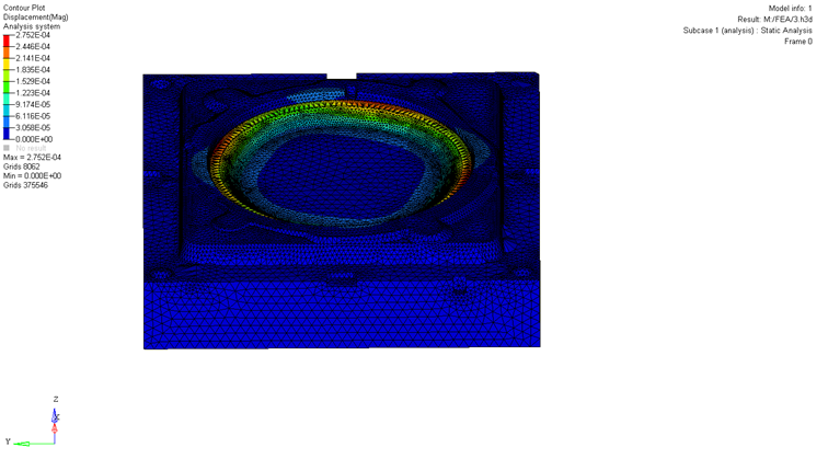
I have a part like following the back plate is constrained and pressure is applied to a round surface on top. I have done linear static analysis. and found the deflection, as follow
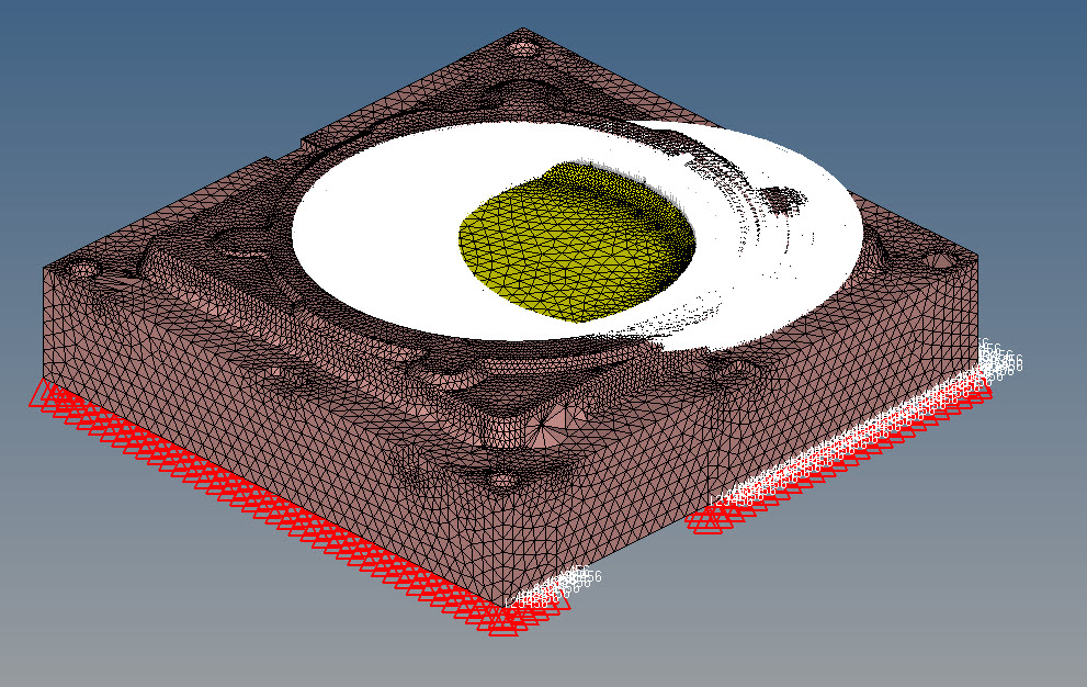
2016-05-06_16-34-24.jpg


mac displacement= 2.7 mm


1 res.png


I have doubled the thickness pressure and constraints are the same as previous one

<?xml version="1.0" encoding="UTF-8"?>2016-05-06_16-39-10.jpg
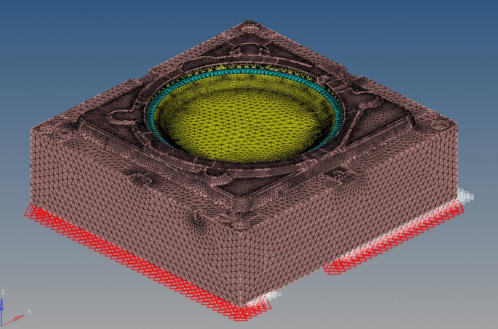


bu the maximum deflection has increased while I expected to have decrease in maximum deflection since I have doubled the thickness and I have more stiffness


Max displacement = 3.2 mm

<?xml version="1.0" encoding="UTF-8"?>2016-05-06_16-42-23.jpg
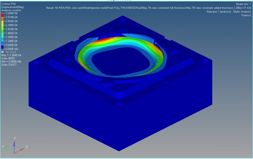
 

I was wondering what can be the reason ? What should be the trend of maximum displacement?? by increasing the thickness should I expect increase in maximum deflection or decrease??

Tagged:

Answers

  • Rahul Rajan_21763
    Rahul Rajan_21763 New Altair Community Member
    edited May 2016

    What type of element you have created 2d or 3d?In which region you have increased thickness.How parts are connected?

    Yes its true that by increasing thickness one can expect decrease in displacement but one needs to understand geometry as well.


    Regards

    Rahul R

  • Altair Forum User
    Altair Forum User
    Altair Employee
    edited May 2016

    The elements are 3D, second order tet. Parts are connected with freeze contact. The added thickness is in opposit z direction as shown in follwing pic

    <?xml version="1.0" encoding="UTF-8"?>2016-05-06_16-42-23.jpg


    and constraints are created on back plate for both model

    Do I have to expect decrease in displacement in z direction while I add thickness in z direction?

    Since my results does not show this trend ( I have increase in maximum displacement while I have added thickness) what could be the reason of this error??

    I really appreciate your help

  • Rahul Rajan_21763
    Rahul Rajan_21763 New Altair Community Member
    edited May 2016

    Hi,

    To me it looks like a intended behaviour. Basically you are increasing height which which let central location to deform more.

    I gave a test run on simplified model to understand  & end up getting same behaviour in that model.See attached screenshot.


    If objective is to reduce displacement then its good to add ribs which increase stiffness.Adding thickness would be a last option that too depending on the shape of geometry.


    <?xml version="1.0" encoding="UTF-8"?>model.JPG

    <?xml version="1.0" encoding="UTF-8"?>output.JPG

  • Altair Forum User
    Altair Forum User
    Altair Employee
    edited May 2016

    Hi Rahul


    Thank you so much for your help

  • Altair Forum User
    Altair Forum User
    Altair Employee
    edited May 2016

    Would you please explain more about adding ribs. My model is solid it is not hollow from inside like yours. Where can I add ribs?

    Would you please advise me regarding the ways I can decrease the maximum displacement with current material

  • Rahul Rajan_21763
    Rahul Rajan_21763 New Altair Community Member
    edited May 2016

    There are many ways to add ribs in solid & shell meshed component.HM Hypermorph or simlab would be best suitable for adding ribs.Let me check some sharable file.

    Meanwhile i request you to perform modal analysis to get modal behaviour.(Mode shape & Freq)