Ge Bracket challenge

Altair Forum User
Altair Forum User
Altair Employee
edited November 2020 in Community Q&A

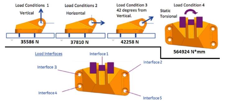
hey! can someone teach me how to apply load to this engine bracket by using hyperworks. i have problem with attach the 42 degree load and torsional load for the bracket. you can see the load type from the diagram. i also attach the iges file of the bracket for your reference. My target is to reduce atleast 20% of its weight. please  contact me if u guys can help me. i really need to know how to put the load. thank you.

<?xml version="1.0" encoding="UTF-8"?>bracket specification 1.JPG
Unable to find an attachment - read this blog

Tagged:

Answers

  • Q.Nguyen-Dai
    Q.Nguyen-Dai Altair Community Member
    edited March 2018

    How you can apply the load for Loadcase 1 & 2 ?

  • Altair Forum User
    Altair Forum User
    Altair Employee
    edited March 2018

    Hi @shahrulnadzrin


    Please see the attached video on how to create loads in 42 deg direction.


    You can use moments panel to create the moment. Use RBEs to create torsion on solid elements. 

    Unable to find an attachment - read this blog

  • Sanjay Nainani_20973
    Sanjay Nainani_20973 New Altair Community Member
    edited March 2018

    Hello,


    For the 42* load case, I can see that your bracket is already aligned at an angle with the Global axis. If this angle is 42* from vertical you can directly apply the load in the Global Z direction.


    For the torsion load case, if you are meshing with solid elements you need to create a rbe2 at the point and the assign the independent node of the rbe2 with moment as solid elements don't have rotational degree of freedom.


    Thankyou

  • yukesh.aero
    yukesh.aero Altair Community Member
    edited March 2018

    You consider angle loading like case example like load value  1000 n 60 degree ,

    For consider point load at point 

    Sin 60 *1000 is the vertical load case

    Cos 60 *1000 is the horizontal load case 


  • Q.Nguyen-Dai
    Q.Nguyen-Dai Altair Community Member
    edited March 2018

    Hello,


    For the 42* load case, I can see that your bracket is already aligned at an angle with the Global axis. If this angle is 42* from vertical you can directly apply the load in the Global Z direction.


    For the torsion load case, if you are meshing with solid elements you need to create a rbe2 at the point and the assign the independent node of the rbe2 with moment as solid elements don't have rotational degree of freedom.


    Thankyou


    You're wrong here. That's solid nodes which have not rotational DoF, not solid elements !


  • Sanjay Nainani_20973
    Sanjay Nainani_20973 New Altair Community Member
    edited March 2018


    You're wrong here. That's solid nodes which have not rotational DoF, not solid elements !


    Correction mistype. 


    Solid Nodes don't have rotational degree of freedom


    Thankyou