How to choose mesh part should be preserved when do JOIN operation
Answers
-
Hi,
Which join operation are you performing?
Do you want preserve the adjacent faces of the joined face? Please give some details.
For example,
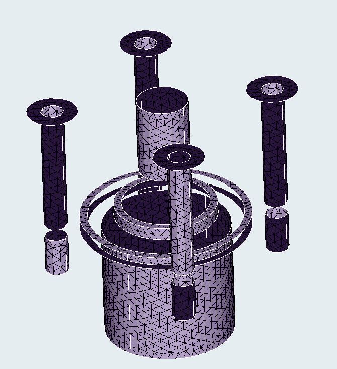
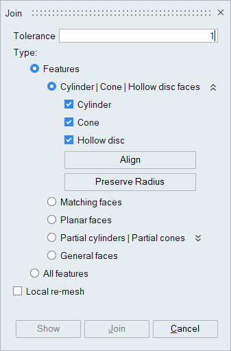
If you are joining 2 cylinders, and both the cylinders (contact faces) having same node count on the circumference, the use the align option and select the axi symmetry body. It will join and create iso mesh on the common face.
Thanks & Regards,
Santhoshkumar
0 -
Thanks Santhosh for your advice.
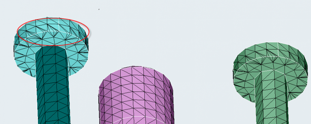
For my case, I have 2 overlap cylinder surfaces, then I want preserve one cylinder with good iso-mesh. I want to know how JOIN function will merge to control.
Your solution is also good. I can use ALIGN option or Preserve Radius in JOIN function to do this.
But when I remesh the adjacent surface to improve mesh quality, it will destroy iso-mesh on cylinder. I am not sure there is any way to freeze mesh during remesh??
<?xml version="1.0" encoding="UTF-8"?>

 0
0 -
If you use the new SL 2019.3, you could try to join directly PARASOLID CAD geometry by creating connected bodies in the boolean panel. It is a very very good way of 'joining' parts.
0 -
Just tried Boolean, CAD parasolid, Combine.
Create connected bodies creates a single part, with one body for meshing. Help test implies it creates a single body with multiple bodies. If I volume mesh, the entire part is meshed.
The help text implies a partitioning surface is created between the two bodies Boolean Combine. If I use cutting plane, the partitioning surface is visible in my simple model. But meshing is done across both volumes.
How does one mesh each volume separately? What? Profile just upgraded from Beginner to Advanced in just 9 months from start? Xlent software.
0 -
After doing the shell mesh of the one big connectedbody, select the mesh body, right-click and choose UNMERGE. You will get the mesh of the original bodies, including the original names.
0 -
Altair Forum User said:
After doing the shell mesh of the one big connectedbody, select the mesh body, right-click and choose UNMERGE. You will get the mesh of the original bodies, including the original names.
Are the two body meshes still connected after UNMERGE? Or does this SEPARATE the two body meshes completely, ready for a smooth Assembly, Join operation, i.e. the joined meshes look perfect at the interface without ugly elements! I need to test. Only buggy (for me) 2019.3, and not 2019.2?
If this works, I would prefer this technique to avoid ugly interface meshes upon Join and Remesh. Like I-DEAS 'partitioned' bodies, in which the solid meshes transition smoothly across the partition.
0 -
VERY NICE! Just like an NX I-DEAS 'partitioned' part!!! I like.
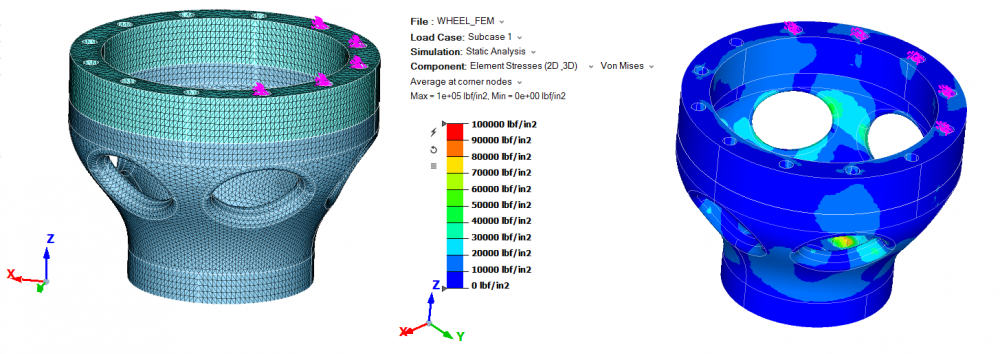
I just tested with the Wheel and Cylinder from my Practice Step for Bolted Sprocket Drive forum post, ignoring the Sprocket
- Prior to meshing, used Geometry, Merge to Wheel and Cylinder into one body, keeping the common face.
- Meshed 2D the single Merged body. Unmerged the body back into the Wheel and Cylinder bodies
- Then 3D Solid meshed each body. Having the bodies separate is advantageous for a lot of reasons
- Did the usual LBC setup, and applied translational and vertical forces to 5 bolt holes, while xyz constraint to the wheel mount holes.
Solved and displayed results to fruition. The two meshed bodies held together, without any need to remesh at the interface. The only difference with I-DEAS is that the single body must have a common average element size at the surface; whereas, I-DEAS could mesh each volume with totally separate element size. But still a very nice surprise.
I supposed if one wanted to test further, one could Assembly, SEPARATE at the interface for whatever reason to actually split the mesh, and reconnect with MPC's for fun.
Entire process took <20 min, just like a Marketing demo (or unlike if humongous transmission housing). Pretty cool, huh?
Though totally different, Simlab is starting to remind of the good-old-days with I-DEAS Master Series, where one could demonstrate the entire modeling process from blank slate, 3D model and solid mesh to results in 10 minutes. Highly graphic, slick in many ways, i.e. Simlab. I'm very low (none) on work the next couple months as contractor during the lockdown, so I'll just keep learning these new tools like Simlab ... and Simcenter 3D (for where its appropriate to import large STEP asm's and revise geometry input to Simlab).
Darryl
0

