RSS Values
Hello to everyone,
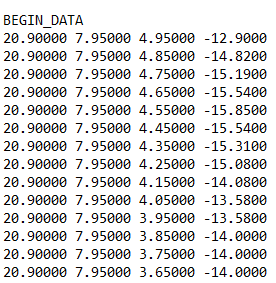
I would like to know how the program is calculating the RSS values on Prediction Planes (last column):

Guessing that the receivers behave in a linear way, in every measuring point, the amplitude and the phase contribution (which is a complex number) of every ray path (using SRT) obtained in the output logs of the transmission matrix should be summed up. Then we can calculate the modulus of the resulting complex number and 10log(abs(result)) for determining the RSS in dbm (maybe I am wrong). Would this be correct? I need to get the RSS values in this way instead of using the output log of the above image because I am trying to combine the results of two transmitters into every measuring point, so the only way to do it is by combining all the measurements in every specific point.
Basically, I want to have in the same result file, the contribution of both transmitters instead of one file per transmitter.
Answers
-
Hello,
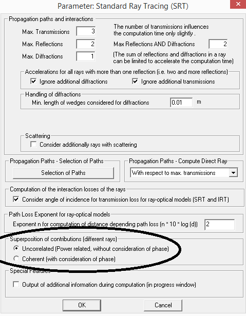
depending on the option selected under the ray tracing settings either the power contributions of the individual rays are added or the phase is considered (coherent superposition):

Results from different transmitters can be also combined in ProMan by loading the first result (.fpp file) and then superpose the second result file .fpp via Edit => Add Data.
Please have a look in the WinProp user manual.
0 -
Additional observations: when you have two antennas, it is not straightforward to obtain the RSS while taking into account phase differences between the contributions from the two antennas. Network-planning results show RSS based on the contributions from all antennas combined, but it doesn't show an interference pattern. That is because in a general situation, transmitters are far apart and in a complicated environment.
To obtain what you are looking for, you can do one of the following:
1. Use a script to manipulate information in the .str file (a detailed output file in ASCII format).
2. If the two antennas are for far apart, use Feko to calculate one combined antenna pattern and use that pattern in WinProp.
3. Perform the entire simulation in Feko if the geometry is not too large in terms of wavelengths.
0 -
Altair Forum User said:
Additional observations: when you have two antennas, it is not straightforward to obtain the RSS while taking into account phase differences between the contributions from the two antennas. Network-planning results show RSS based on the contributions from all antennas combined, but it doesn't show an interference pattern. That is because in a general situation, transmitters are far apart and in a complicated environment.
To obtain what you are looking for, you can do one of the following:
1. Use a script to manipulate information in the .str file (a detailed output file in ASCII format).
2. If the two antennas are for far apart, use Feko to calculate one combined antenna pattern and use that pattern in WinProp.
3. Perform the entire simulation in Feko if the geometry is not too large in terms of wavelengths.
Actually, I am trying to manipulate the .str file. The only thing is I do not really know how to get the received power by using the data it provides. My best thought is by using the transmission matrix coefficients (real part and imaginary part) add all the values of every path for every specific measuring point, then get the modulus for multiplying it to the transmitted power. Then the result should be converted from Watts to dbm, but honestly I do not know if this is correct enough. I am trying to compare obtaining these values in this way and the ones provided by the ASCII file from Winprop and it does not coincide. So I guess my interpretation is not good. Would you suggest how to do it with the provided data in .str file?
Thank you so much for your attention.
0 -
Okay I see. The problem is that I think that maybe that result is not accurate enough (maybe I am wrong). I am interested in seeing the pattern of the distribution of the RSS along the prediction plane.
0 -
Altair Forum User said:
Hello,
depending on the option selected under the ray tracing settings either the power contributions of the individual rays are added or the phase is considered (coherent superposition):
<?xml version="1.0" encoding="UTF-8"?>

Results from different transmitters can be also combined in ProMan by loading the first result (.fpp file) and then superpose the second result file .fpp via Edit => Add Data.
Please have a look in the WinProp user manual.
Okay I see. The problem is that I think that maybe that result is not accurate enough (maybe I am wrong). I am interested in seeing the pattern of the distribution of the RSS along the prediction plane.
0 -
By default the power superposition is considered in ProMan for the superposition of the individual rays (representing the mean signal level), but also the coherent suerposition (considering the phases) can be activated, which then represents the fast fading (probably the pattern you are expecting).
Similar process can be applied for the superposition of the results from two transmitters:
- Either the power values of the two transmitters can be added, which represents then the expected mean signal level considering both transmitters
- Or the phases for the superposition can be considered, which would assume that both transmitting antennas are synchronized. In this case the rays from both transmitters can be superposed based on the fieldstrength and phase values given in the .str files (one .str file per transmitter). The .str files can be also generated using the WinProp API.
0