Debugging Guide for Linear Analysis – Modelling Checks

 Altair Employee
When building a CAE model, there are a lot of information you should input in order to successfully run your analysis and of course, to have reasonable results. In this article we will show a couple of tools and features we have available within HyperWorks and OptiStruct to validate your model and avoid error messages and wrong results.
Unit System
Even before start meshing your geometry, it is important to keep in mind the unit system that will be used for your particular model. This is because OptiStruct will accept whatever it is provided as input, without giving any warning as it will not be able to recognize any unit system discrepancies. Therefore, it is a user responsibility to work with consistent unit systems in HyperWorks for modeling and analysis. The table below presents various systems of consistent units. The most used systems are highlighted:
| Unit System | Length | Mass | Force | Time | Density | Stress | Gravity | |
| MKS | m | kg | N | s | kg/m³ | Pa | 9.81 m/s² | |
| MMKS | mm | kg | N | s | kg/mm³ | MPa | 9810 mm/s² | |
| MPA | mm | t | N | s | t/mm³ | MPa | 9810 mm/s² | |
| CGS | cm | g | dyn | s | g/cm³ | dyn/cm² | 981 cm/s² | |
| IPS Std | in | pounds | lbf | s | lb/in³ | psi | 386.09 in/s² | |
| FPS Std | ft | pounds | lbf | s | lb/ft³ | lbf/ft² | 32.17 ft/s² | |
Element Quality
Under Validate > Element Quality, the user can verify the basic quality of 1D, 2D and 3D elements:
- 1D subpanel: Checks for 1D free elements and rigid elements inter and double dependency.
- 2D and 3D subpanel: Checks for 2D and 3D elements quality. The main criteria used for them are warpage, aspect ratio, skew, jacobian and tet collapse (3D only).
The user can update the values based on his/her company’s mesh criteria. If there are no criteria available, the default values from HyperWorks are considered a good starting point.
A similar panel for this type of verification is under Elements > Auto Quality.
Check Elems Panel Documentation
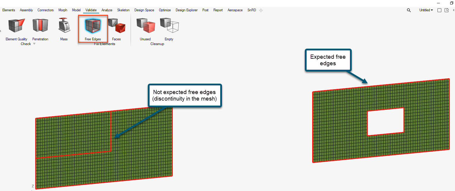
Free edges (2D elements)
Under Validate > Free Edges, the user can check the connection of 2D shell elements. Free edges are normally found around the outer perimeter of a part or around openings within the part. Free edges found in your model are displayed as red plot elements in their own component called ^edges. This is a good indicator that your mesh is properly connected or if there are any discontinuity.
You can use equivalence to remove the coincident nodes, based on a search tolerance which you specify.
Tip: For bigger models, wireframe or transparent view can make the visualization easier.
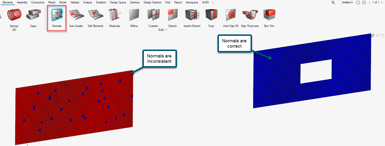
Normals (2D elements)
Under Elements > Normals, the user can check the normals of elements. The normal of an element is determined by following the order of nodes of the element using the right-hand rule. Ideally for each surface, the normals should be consistent and pointed to the same direction. If this is not the case, the user can have wrong results for analysis that involve bending effects or layer (top/bottom) dependency.
Normals can be reviewed showing a vector or by colors. A vector shows in positive normal direction, while the color mode shows the positive side of a shell or surface in red and the negative side in blue.
This type of inconsistency is usually found when the user manually created elements in the model and can be easily adjusted using the adjust option.
Faces (3D elements)
Under Validate > Faces, the user can find free faces in your model where 3D elements are separated, and highlight those areas. Ideally the user should expect a red skin mesh wrapping the solid component and empty in the inside. If this is not the case, it means that the 3D mesh is not fully connected.
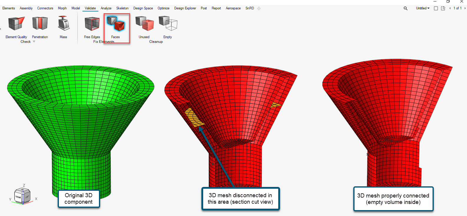
Once the free faces are located, you can use equivalence to connect the mesh, based on a tolerance specified by you.