Hi,
i have a problem regarding the correct visualization and therefore results of my model.
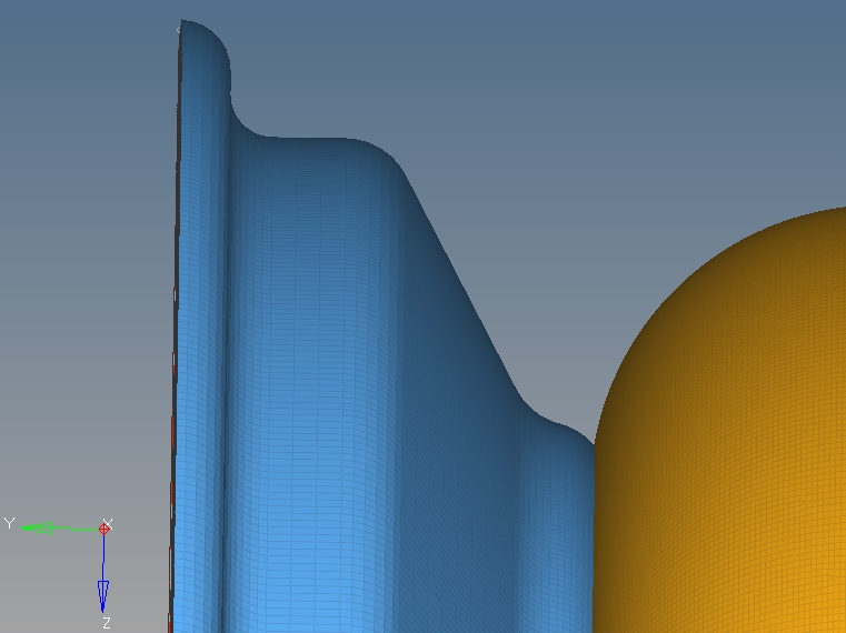
I have a wheel model which is going to be made of carbon fiber. It is kind of an T-shape, but not really, see following screenshots.
<?xml version="1.0" encoding="UTF-8"?>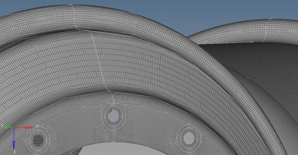
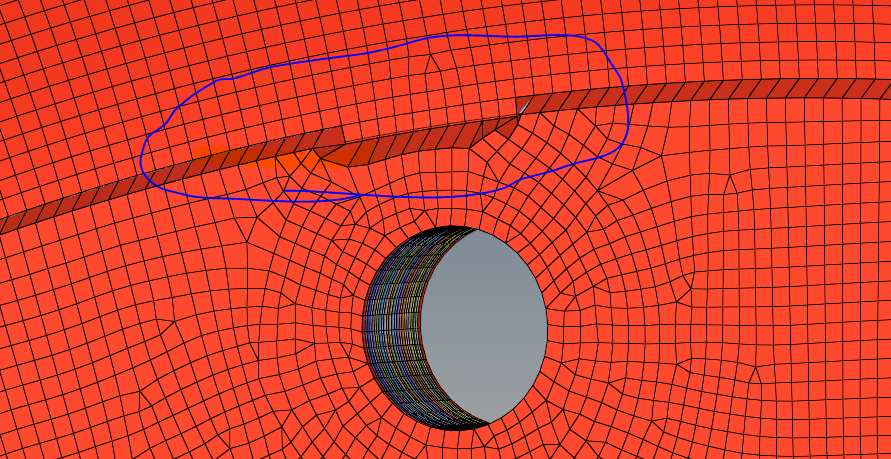
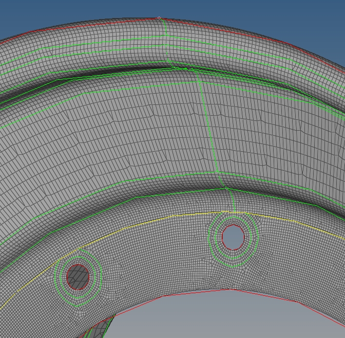
After creating the laminate, the curved surfaces intersect even though I am using the interface laminate feature with two sublaminates. The element normals of the blue surface face in the y-direction, the element normals of the yellow surface and vertical surface face in the -y-direction.
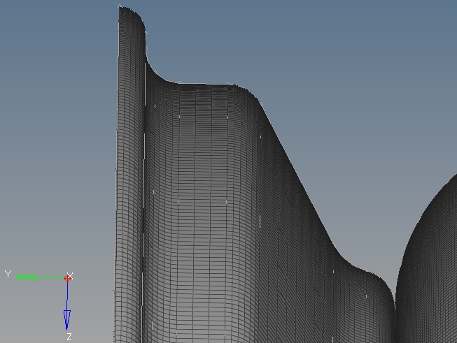
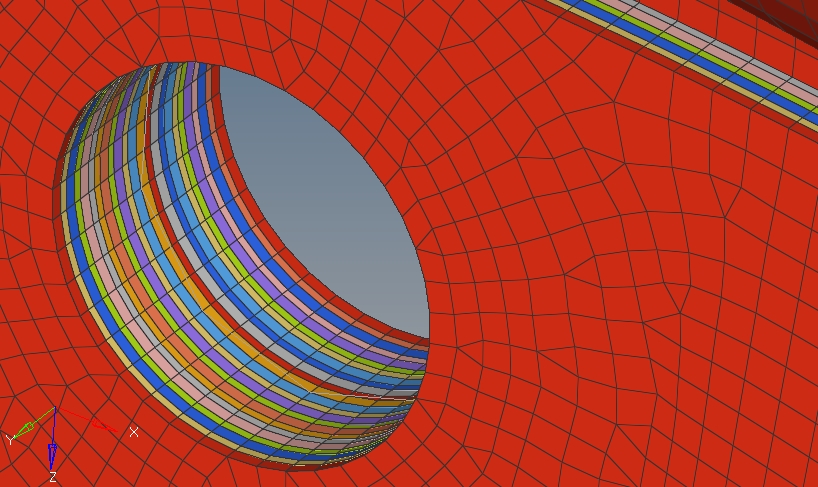
The interface laminate feature works on the middle, vertical surface of the wheel, but you can also see that the laminates of the shells intersect while the vertical surface works properly. This is why I have a sharp step in the front of the wheel and a less sharp step in the back of the wheel and it looks like the plies are interrupted.
<?xml version="1.0" encoding="UTF-8"?>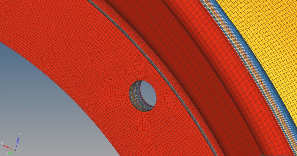
<?xml version="1.0" encoding="UTF-8"?>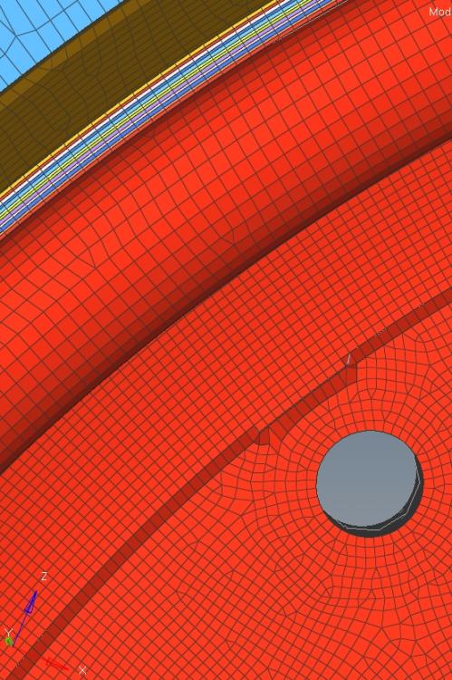
So I would like not to have those steps or intersection plies but instead a smooth transition from the shells to the vertical surface as it is in the 2D model. I attached many pictures so it is better to explain and imaginable. Also I considered that i have to choose the interface plies with regard to the element normals:
<?xml version="1.0" encoding="UTF-8"?>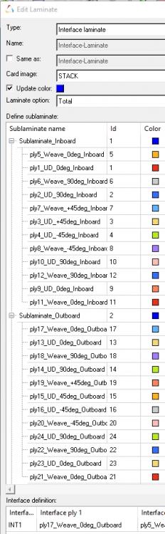
Pleas let me know if you have further questions to this problem. I also found different forum posts but they do not help me because they are more like real T shapes where as mine is not.
Thanks in advance!