Questions about composites modelling
Hello,
I am currently working on a project where I have to optimize the monocoque structure of a lightweight vehicle. The materials used are carbon fiber reinforced polymer and aramid fort the core. In some places, there have to be inserts so that for example the belt or the seating can be fixed. The goal of my task is to make a composite optimisation with Hypermesh/Optistruct for the monocoque and particularly the insert zones.
On the picture below you can see the structure of the insert zone. First there is a sandwich-structure with layers of CFRP (A and C) and aramid (B), which forms the monocoque structure. Then I have the insert (E) which is glued on the top of the CFRP-layers (C). Another CFRP-Layers (D) are laminated on the top of the insert zone, except the threaded rod of the insert.
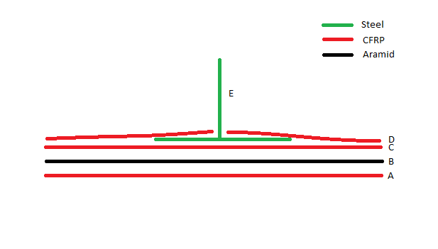
I have some difficulties to simulate this structure on Hypermesh. Insofar as I have several layers (C) of CFRP between the aramid and the insert, the insert is merged in the CFRP layers (in the 2D detailled element representation). I want to have the insert (E) on the top of the last CFRP layer. Do I have to create a contact between the last CFRP layer and the insert?
On the picture below you can see my problem (the D-Layers are not shown in this view).
<?xml version="1.0" encoding="UTF-8"?>
I have the same problem to put the CFRP layers (D) on the layers (E) at the places where there is no insert (around the insert).
Thank you for any help,
Eric
Answers
-
Hi Eric,
You can make the flat part of the layer E as a part of the laminate. Did you try this?
0 -
Hello,
Altair Forum User said:Hi Eric,
You can make the flat part of the layer E as a part of the laminate. Did you try this?
I didn´t try this but E isn´t a composite layer, it is a simplified 3D steel part (see picture below) which is glued on a group of composite layers C and laminated with another group of composite layers D.
Eric
0 -
Eric,
Two ways, you can model the E as shell element and include it as a part of laminate (material can be different, PSHELL)
or
Create interface laminates.
0 -
Hello,
Thank you for your answer. Can you maybe short explain how I can include a PSHELL or PSOLID element in the laminate ? I´m a beginner and I only managed plies with the PCOMPP property.
Furthemore I still don´t see how I can create an interface laminate with a full steel part (I dont want to optimise this part, just the CFRP layers around this part).
Eric
0 -
HI Eric,
sorry for my typo error, stack goes with ply + pcompp but PSOLID needs a different property(PSOLIDLS). I will create a sample model for you and share with you soon
0 -
the steel part is glued with both C and D ply so I think you don't need to modeling contact
I made this pcompp as demo (but I am not sure ...)
only C and D need to join with E, below of them are B (you made solid, didn't you?) and A
0 -
You are quick /emoticons/default_smile.png' srcset='/emoticons/smile@2x.png 2x' title=':)' width='20'>
0 -
Hello,
Thank you both for your answers and your very interesting model tinh !
You can see on the picture below wat I want to have at the end with a cut on the XZ-plane.
Here I just make translations of each part to show you but actually I want to ensure that the steel part E is overhead the layers of the group C independently from the thickness of the layers C (and the same between the groups C and D). It´s important for me especially for the optimisation part where the thicknesses are changing.
<?xml version="1.0" encoding="UTF-8"?>
0 -
I think with PCOMPP, optistruct will consider it because we define STACK of PLIES with specified order, so Optistruct will realize that E is 'above' C and 'below' D .
Am I right @Prakash Pagadala ?
Or we actually have to set ZOFFS ?
If any, STACK is not much meaningful.
0 -
Hello,
I worked on my model in the last few days and I have another questions about it.
On the picture you can see the five under-layers A, then the aramid-layer B and the group of layers C and D. In blue the insert E.
On the upper zone, I made a laminate with :
- Five CFRP plies under the insert
- Five CFRP plies over the insert
- Two steel plies (thickness 1 mm between the CFRP plies and 20 mm for the rod)
<?xml version="1.0" encoding="UTF-8"?>
As I said, I don´t want to optimize the two steel layers in blue (which are the insert). Is it possible to let Optistruct optimize just some layers from a laminate ?
Am I right when I consider the insert as two plies instead of an independent PSOLID component ?
Furthemore, is it possible to improve the meshing of the rod (which is a ply) ?
Thank you for your answers.
Eric
0 -
Hi,
It is OK to consider the inserts as SHELL when the thickness is not significant.
You can use CONST on DSIZE to provide a constant thickness to the insert which will retain its original thickness throughout the optimization,
0