Stone chipping is the damage done to exterior vehicle parts, typically due to the high velocity impact of heavy particle materials such as rocks and stones. If the particles are loose on the road surface, as the vehicle drives over these materials, the particles are lifted and ejected by the vehicle tires. These impacts can be at high velocities and can damage the vehicle surfaces. This damage usually appears in the shape of paint removal or small deformation, in some cases it can be of higher importance if the impact is located on a crucial component of the vehicle.
Furthermore, with the increase in popularity of electric vehicles, which are typically quieter than Petrol or Diesel, the acoustic requirements also have to be considered. Since electric engines are so quiet, the noise experienced by the passengers due to the engine is low. This means that the minimum impact on the vehicle coming from any object produces a noticeable disturbance in the passenger cabin.
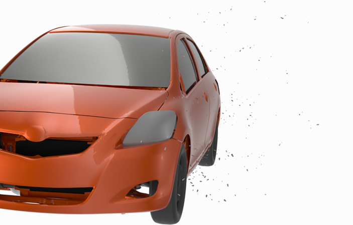
Altair® EDEMTM can help improve vehicle exterior designs, and protection placement, by modelling stone impacts at different levels of complexity. By prescribing quantity of stones being lifted and their initial velocity and direction EDEM can help designers by:
- Postprocessing the number, location and intensity of impacts on the car exterior and underbody
- Coupling EDEM to MotionSolve to control the vehicle movement and wheel rotation
- Utilizing EDEM´s FlexTire® plugin to increase realism on the tyre model by including pressure and deformation
- Calibrating EDEM wear models to give accurate damage predictions and visualize impact deformations
Attached you can find a stone chipping model setup in EDEM. The key steps to setup a stone chipping EDEM simulation are:
Step 1 – Materials
In general, EDEM materials should be calibrated, or can be picked from existing material model databases:
In this case the focus on material preparation should be on capturing an accurate size distribution, shape and density rather than the interaction parameters such as friction or cohesion.
Step 2 – CAD
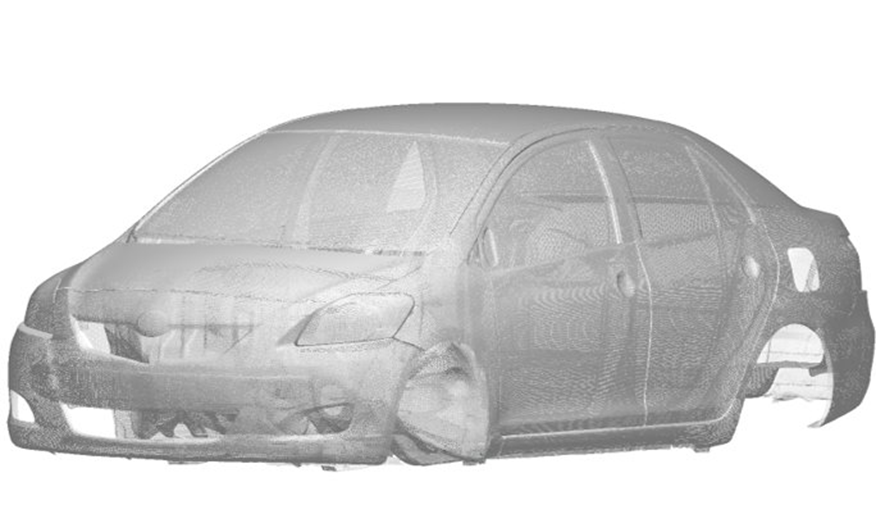
EDEM supports many file types such as STL, STEP, IGES. Geometries are imported to EDEM via the Creator > Geometries > Import Geometry section. You can choose either the default mesh, which is optimized to capture the geometry shape while minimizing the mesh elements, or choose a manual mesh size. You may want to manually select the mesh if your analysis includes wear. Wear is plotted per triangular mesh element, as such the quality of the meshed surface influences the analysis.
Step 3 – Introduce Material
Starting simple, the user can prescribe the quantity, initial velocity and direction of the stones by utilizing the feature “Spray Pattern”.
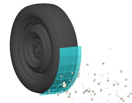
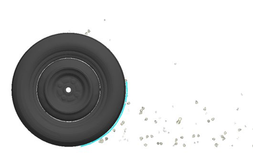
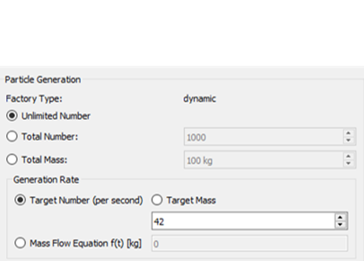
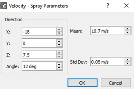
For more advanced models with MotionSolve and FlexTire, an offroad surface can be created with volume packing selecting a material from the Soils Starter Pack.
Some gravel like particles can be spread on top of a flat plate pretending to be some loose rocks on the surface of a paved road. To do so, a simple factory above a flat road surface would do the job by creating a few scattered rocks with the rainfall method. Please note that this scenario is only valid if using the Flextire plugin, as tire deformation would be necessary to pick up the loose rocks and eject them.
Step 4 – Assign Kinematics
If we are working with the simpler setup of prescribing stone quantity, direction and initial velocities, then there are no kinematics required.
If the model created is a coupled EDEM-MotionSolve solution, where MotionSolve controls the vehicle, no kinematics would be required on the EDEM side. The FlexTire module can be used in addition to the coupling.
Step 5 – Running the simulation
It is typically recommended to run EDEM models utilizing 1 or several GPU devices to have the model results as quickly as possible. This recommendation is also valid for the Stone chipping application but if the model simulated has prescribed stone quantities, directions and velocities it can be run with less computational power. In this setup usually the particle numbers are small and even running the model in several CPUs could be enough.
Step 6 – Analyzing results
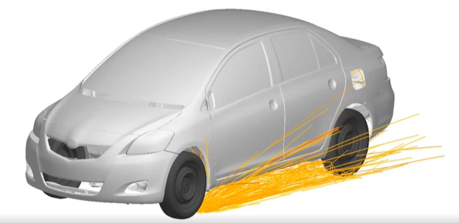
Once the simulation is finished it is straight forward to visualize stone trajectories and locations of impact against the car exterior and underbody. With this data, comparison between designs is already possible, enabling designers to ensure the number of impacts are reduced and protection is placed properly.
However, more advanced postprocessing is possible if using the Wear models available in EDEM:
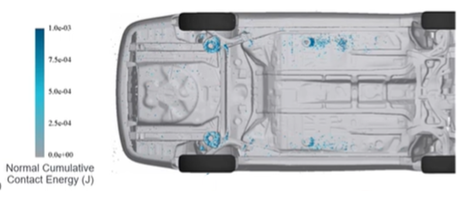
- Relative Wear: If this model is selected for the simulation EDEM will display accumulated impact energy (normal and tangential) in each mesh element of the car exterior and underbody. This output allows for clear understanding of most frequent impact locations and the energy values allow for an easy comparison between designs. Wear calibration is unnecessary for the Relative Wear model.
- Oka Wear: This wear calculation offers material removal rate based on impacts. Not only does it highlight the areas potential wear, but it also indicates the quantity of material removed from that area if the material model is calibrated. This analysis is valuable both as a standalone case or in comparison with other design iterations.
For further information please see the following:
Learn more about the PM’Flextire by Pratt Miller:
See how EDEM can be coupled to Altair MotionSolve:
https://learn.altair.com/enrol/index.php?id=157