Product = GENESIS
Shape optimization in GENESIS is commonly used to design the external shape of structures and/or its members.
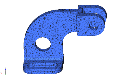 Figure 1
However, the same techniques used for typical shape optimization problem can also be used to design details or features of structures. In this example, we will show that shape optimization can be used to design the dimensions and locations of a circular hole located on a bracket.
It should be noticed that holes are commonly used to lightening structures. Holes are also used to pass through other structures or structural components.
To design the location and dimension of the hole in the structure in Fig. 1 we will use 5 steps. These steps are performed using the GENESIS GUI, Design Studio.
Step 1: Create Morphing Boxes
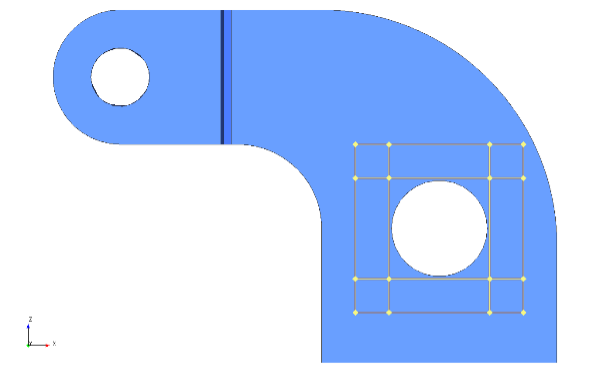 Figure 2
 Morphing boxes which are also called domains are normally placed around the structure. In this case we will place one domain around the hole and 8 additional domains surrounding the first one. These additional domains are called transition domains and are used to minimize distortions of the finite elements that are close to the ends of the main domain. The nine domains are showed in Fig.2. Notice that only the borders of the domain are shown.
Step 2: Create Morphing Vectors
For this problem, three morphing vectors are created. The first two are to design the vertical and horizontal position of the hole. The third morphing vector is used to design the diameter of the hole.
 Figure 3.a
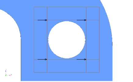 Figure 3.b
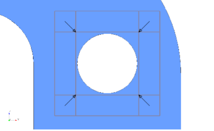 Figure 3.c
Fig. 3.a shows four vectors applied vertically on the 4 corners of the center morphing box that covers the hole; these four vectors form the first morphing vector. Fig. 3.b shows four vectors applied horizontally on the 4 corners of the center morphing box; these four vectors correspond the second morphing vector. Finally, Fig. 3.c shows four vectors on 4 corners pointing to the center of the center morphing box and they correspond to the third morphing vector.
Step 3: Verify the Morphing Vectors
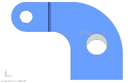 Figure 4.a
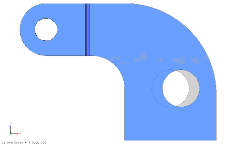 Figure 4.b
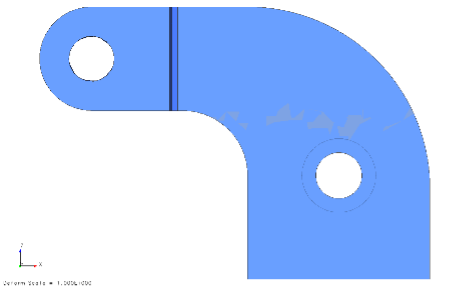 Figure 4.c
Fig. 4.a shows the first morphing vectors capability of moving the hole upward. Fig. 4.b shows the second morphing vectors capability moving the hole sideway. Fig. 4.c shows the third morphing vector capability of reducing the diameter of the hole. On the pictures above the grey shadow represent the original shape and help understand the relative position of the hole
These last 3 pictures confirm the desired effect of the individual morphing vectors. The movement above represent a positive and unitary movement of each of their corresponding design variables, one at the time. The Optimization process will find the best combination of values for the design variables.
That’s all for now. In the upcoming blog, this topic will be continued, with the results of optimizing the structure using the morphing vectors described in this blog.