CAD Modeling in feko
Hi,
I need help regarding modeling a winding in FEKO.
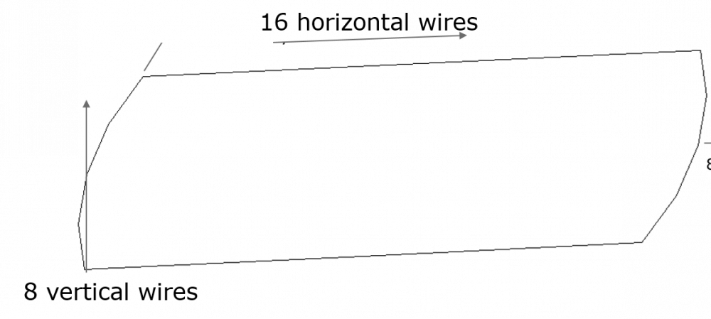
I would like to model a winding with 136 turns. To be clear I have attached a wire model. I would like to have a winding with 16 horizontal layers of same shape as shown in the figure and 8 vertical layers. I also attached a sample of 3D model with 16 horizontal layers which should look like. I was using a polyline to draw layer by layer, but it is taking a lot of time to model it.
Could anyone suggest me some other alternative ways or easy process to do this. Or could anyone write a lua script to altleast generate a single layer of wire (fig:wire:2) an dthen remaining I hope I can do it.
Thanks
Answers
-
Hello Sra,
Scripting is definitely the way to go if you want to create geometry such as this. I don't see a model attached (did you forget) and thus I can't provide a script with your model, but I can create something similar and then you can adjust it.
Using script recording, a basic polyline can be created and then CADFEKO generates the code for you. The result for my model is:
properties = cf.Polyline.GetDefaultProperties() properties.Corners[1].N = '0' properties.Corners[1].U = '-0.7' properties.Corners[1].V = '0.2' properties.Corners[2].N = '0' properties.Corners[2].U = '0.7' properties.Corners[2].V = '0.2' properties.Corners[3] = {} properties.Corners[3].N = '0' properties.Corners[3].U = '0.7' properties.Corners[3].V = '-0.2' properties.Corners[4] = {} properties.Corners[4].N = '0' properties.Corners[4].U = '0.6' properties.Corners[4].V = '-0.5' properties.Corners[5] = {} properties.Corners[5].N = '0' properties.Corners[5].U = '-0.7' properties.Corners[5].V = '-0.5' properties.Corners[6] = {} properties.Corners[6].N = '0' properties.Corners[6].U = '-0.7' properties.Corners[6].V = '0.2' properties.Label = 'Polyline1' Polyline1 = project.Geometry:AddPolyline(properties)
You can then adjust this to create the model that you want. It would probably be something like:
-- CADFEKO v2017.2-305925 (x64) app = cf.GetApplication() project = app.Project local function addPoints(points, base_dr, base_dz, last_dr, last_dz) local point = {} point.N = '0+' .. base_dz point.U = '-0.7 - ' .. base_dr point.V = '0.2 + ' .. base_dr table.insert(points, point) local point = {} point.N = '0+' .. base_dz point.U = '0.7 + ' .. base_dr point.V = '0.2 + ' .. base_dr table.insert(points, point) local point = {} point.N = '0+' .. base_dz point.U = '0.7 + ' .. base_dr point.V = '-0.2' table.insert(points, point) local point = {} point.N = '0+' .. base_dz point.U = '0.6' point.V = '-0.5 - ' .. base_dr table.insert(points, point) local point = {} point.N = '0+' .. base_dz point.U = '-0.7 - ' .. base_dr point.V = '-0.5 - ' .. base_dr table.insert(points, point) local point = {} point.N = '0+' .. last_dz point.U = '-0.7 - ' .. last_dr point.V = '0.2 + ' .. last_dr table.insert(points, point) end -- Created geometry: polyline 'Polyline1' properties = cf.Polyline.GetDefaultProperties() Corners = {} local dz = 0.05 local dr = 0.05 max_ndr = 1 max_ndz = 3 for ndr = 0, max_ndr do for ndz = 0, max_ndz do if ndz == max_ndz then addPoints(Corners, dr*ndr, dz*ndz, dr*(ndr+1), dz*(ndz+1)) else addPoints(Corners, dr*ndr, dz*ndz, dr*ndr, dz*(ndz+1)) end end end properties.Corners = Corners Polyline1 = project.Geometry:AddPolyline(properties)
Note that the code above only shows the point. It is not correct. You have to adjust the loops and code to ensure that the wires don't cross and windings are created they way you want them. As an example, my example does one stack (in Z) correctly, but then goes down to bottom instead of doing the second stack from the top down.
0 -
Hi JIF,
Thanks for your reply. I will try your code.
Attached is my solid model. I guess if I used this script I think I will get a square shape rather than the shape of my solid model.
I will try what I can do. /emoticons/default_smile.png' srcset='/emoticons/smile@2x.png 2x' title=':)' width='20' />
Regards,
Sravan
0 -
Hi JIF,
Unfortunately I couldnot implement the code according to my requirements. If possible could you please go through the script and make necessary corrections. The script works but the shape of the winding is not what I expected.
Could you go through it once again and provide me necessary suggestions?
Thanks,
LG,
Sra
0 -
Hello Sra,
Let me first provide you with some suggestions so that you can solve the problem yourself. Is suspect the biggest problem that you are having is that you are trying to work in a non-aligned axis system. Use the Align tool to orientate the geometry in Coil.cfx to the global axis. It should then look like this:
<?xml version="1.0" encoding="UTF-8"?>
Now that the geometry is aligned, it is easier to define the coil. After the coil has been defined, the reverse alignment can be applied to both (or applied to the coil and deleted from the geometry).
It is difficult for me to help with the coil since I don't know where the coil should be (it is also beyond what I usually do on the forum - we are here to help, not do the work). ;-)
I did take a look at the script and made some changes. After my changes, the coil looks like this (I assumed the coil's required placement, but that is easy to change).
<?xml version="1.0" encoding="UTF-8"?>
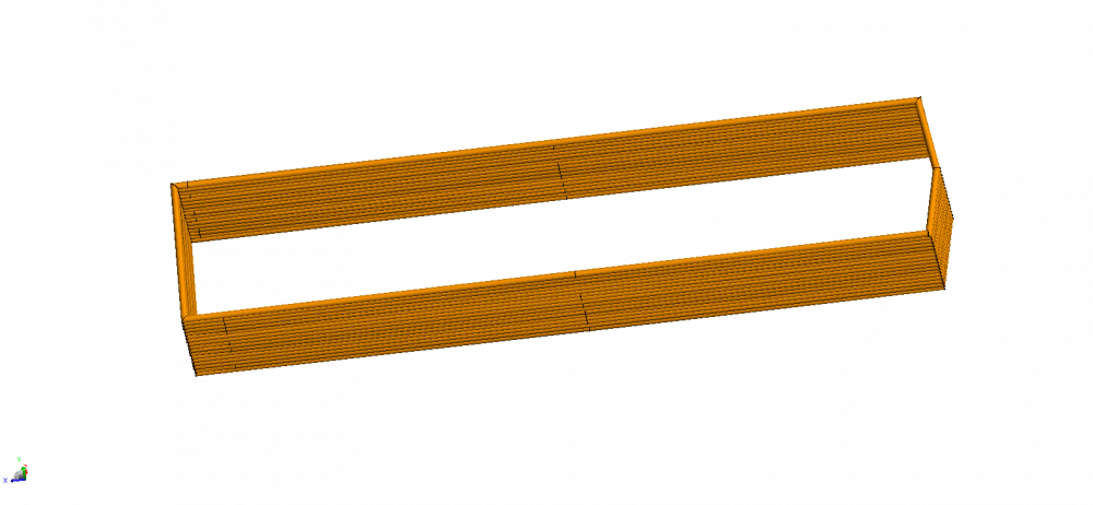
The only part that I think you should figure out is how to ensure the wires should be created to ensure that they don't cross other wires. See the image below for the areas that need to be fixed. Those wires that go from the top to the bottom (vertical) need to be changed. These changes are simply in the FOR loop - basically you need to count the z-levels from 0 to max and in the following stack, count from max to 0 (0, 1, 2, 3, 3, 2, 1, 0, 0, 1, 2, etc.). Try to do this yourself and post the result on the forum for the next user. If you really get stuck, I'll try to help later in the week.
0 -
Sra, I felt generous and modified the script to a state that should work (I don't see overlapping wires). You will see that I moved the first point out of the loop (was a mistake in my initial script). Your work will be to change the script so that the coil is located correctly w.r.t. the geometry and then add an alignment transform (or set a workplane on the polyline) to orient it correctly in your model (this should be very easy for you to do).
Good luck with your project!
0 -
Hi JIF,
Thanks a lot for yor suggestions and providing me necessary suggestions. It was really helpful for me.
I think I can continue now further
0 -
Hi JIF,
I have a small problem regarding the script.
There is always an intersection of wires in the top and bottom part of the winding (to say specifically: at the transition from layer x to layer y). If I just look at the wires there is not any intersection, but when i sweep the wire with an ellipse of certain radius or mesh it with a wire radius then there is an intersection of wires in the top and bottom. I tried myself changing the for loop but still the same problem occurs again. Could you please say how can i define parameters at the transition of layers.
0 -
I don't know what you are trying to do with the sweep or why you are sweeping. Without and example, I can't help you. If you provide me with your model and your current script, I can have a look to see if I have advice.
0 -
Normally I would like to assign the wire (winding) with a certain wire radius. So I used an ellipse to 'pathsweep' the complete winding.
I also changed some of the for loop in the script inorder to get what I need. Doing this, avoids some of the intersections, but during the transition of layer 'X' to layer 'y' there is an intersection which is only visible when I assing a certain wire radius. I have an idea of increasing the height of the wire at the corner only where intersection occurs but I am out of ideas.
I have attached my model and script.
0 -
Before you try to fix that, are you sure that you want to model your coil with cylinders and not using wire segments? Wire segments would be much more efficient and probably won't even result in errors for those overlaps (still give good results). Wire segments assume axial symmetry, but that is usually not a problem for coils (sure, it is not true on the sides, but even then it is not a dominant factor in my experience).
You can obviously revise the wire spacing and wire radius to resolve your problem. If that is not an option, you need to figure out a way to wind the coil so that it does not result in overlaps. I don't have any good suggestions now - maybe someone else on the forum does?
0