Meshing errors
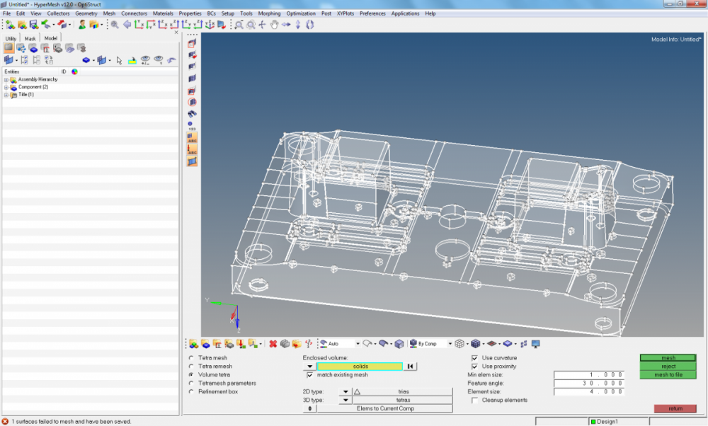
I'm trying to mesh a part that is, by my standards, very simple. It is designed in Solidworks and imported to HyperMesh in .STEP format. I have been trying to use tetramesh with trias/tetras and a 0.100 element size, which produces errors 'shell elem region incomplete' followed by '1 surfs failed and saved'. The resulting mesh is a 2D surface instead of a 3D solid. All I would like is assistance in making the mesh solid and eliminating these errors.
Also for some reason I can't upload any files - not .hm, not .step, not .iges. So I have attached a picture of the design if that helps at all
<?xml version="1.0" encoding="UTF-8"?>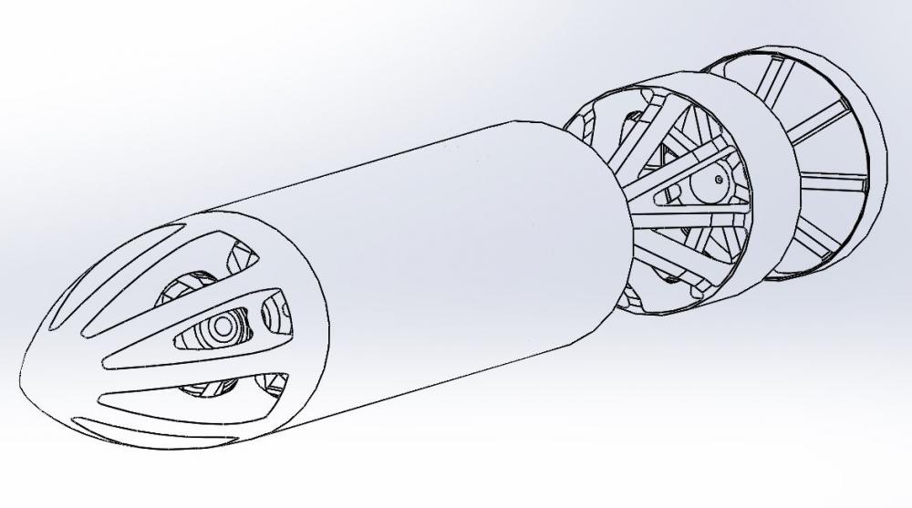
Answers
-
Altair Forum User said:
I'm trying to mesh a part that is, by my standards, very simple. It is designed in Solidworks and imported to HyperMesh in .STEP format. I have been trying to use tetramesh with trias/tetras and a 0.100 element size, which produces errors 'shell elem region incomplete' followed by '1 surfs failed and saved'. The resulting mesh is a 2D surface instead of a 3D solid. All I would like is assistance in making the mesh solid and eliminating these errors.
Also for some reason I can't upload any files - not .hm, not .step, not .iges. So I have attached a picture of the design if that helps at all
Hello,
from when you saw error message '1 surfs failed and saved', press escape to escape tetramesh panel
press F5 switch entity to 'surfs', click 'surfs' > retrieve > mask > reverse all, you will see a surface that has error ( i thick it has free edges)
press F11 and fix the red lines you see if any
0 -
I'm still having issues. No red lines appear when I follow your instructions. I can find the surface by searching for the ID number but do not know how to proceed further. I'd like to just send the .hm to you but I can't upload it to the forum. Can I send it to you in an email?
0 -
Altair Forum User said:
I'm still having issues. No red lines appear when I follow your instructions. I can find the surface by searching for the ID number but do not know how to proceed further. I'd like to just send the .hm to you but I can't upload it to the forum. Can I send it to you in an email?
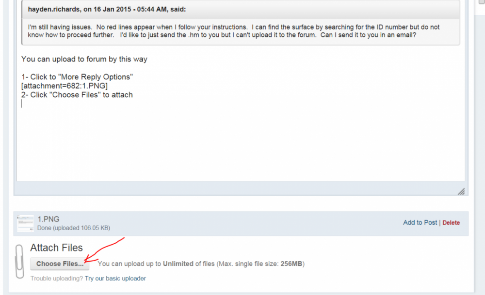
You can upload to forum by this way
1- Click to 'More Reply Options'
<?xml version="1.0" encoding="UTF-8"?>
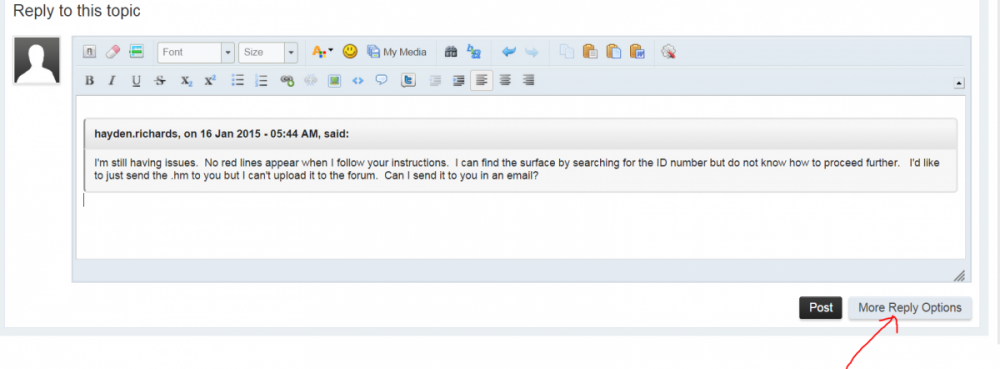
2- Click 'Choose Files' to attach
0 -
Altair Forum User said:
I'm still having issues. No red lines appear when I follow your instructions. I can find the surface by searching for the ID number but do not know how to proceed further. I'd like to just send the .hm to you but I can't upload it to the forum. Can I send it to you in an email?
Another way to process Tetramesh:
F12 > surfs > select surfaces of component > select element type is 'trias' or 'R-trias' > mesh
3D>tetramesh > select trias element > mesh
(before tetrameshing, please check and fix free-edges of shell elems by Shift+F3)
0 -
hayden.richards
Please note , you will have to zip certain files and upload the zipped file for security reasons,
you can also change the extension of the file to say .jpg and upload it , in which case just add a note saying you changed what extension to what,
0 -
I'm trying your suggestions. Meanwhile, I'm attaching the file. Please let me know what you think. Thanks,
0 -
@hayden.richards:
It's a complex geometry. Don't try make your mesh with 'one click'
/emoticons/default_smile.png' alt=':)' srcset='/emoticons/smile@2x.png 2x' width='20' height='20'>
At your place, I'll check symmetrical possibility of model to simplify the work.
It's better also to divide the big and complex solid into several small solids and do the mesh solid by solid to obtain the final ones.
For a good 3D mesh with TET10, I think you need some time. That can not be done within one working day
/emoticons/default_smile.png' alt=':)' srcset='/emoticons/smile@2x.png 2x' width='20' height='20'>
Good luck!
0 -
-
0
-
Dear Rahul Ponginan
thank you for the link, it helps a lot, but i have one more question, sry for that
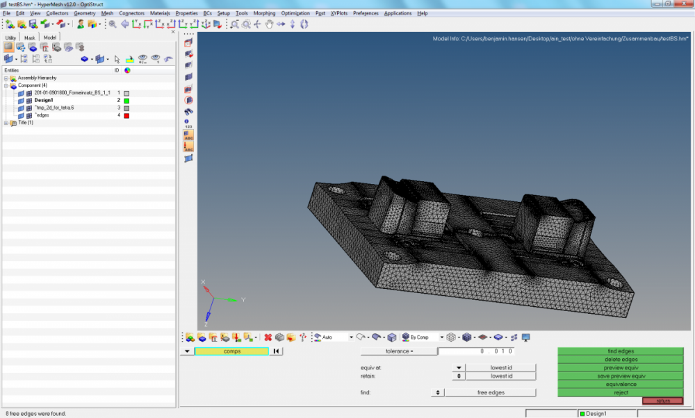
see at my Picture below, i have found 8 free edges, may that is my Problem for meshing, (before i had delete two duplicated elements)
now, how can i delete this free edges, or what can i now do?
0 -
-
codiak,
Free edges are defined as a pair of nodes identifying an element edge that are not shared with another element. Free edges are normally found around the outer perimeter of a part or around openings within the part. Free edges found in your model are displayed as red plot elements in their own component called ^edges.
Free edges within a field of elements typically indicate a discontinuity within the mesh. Such discontinuities may be intentional, such as crack modeling for durability simulation--or unintentional, due to geometry discontinuities, meshing methods or component boundaries. In cases where the mesh has a discontinuity, there will typically be more than one node at approximately the same location in space. Such nodes are called “coincident'.

You can use equivalence to remove the coincident nodes, based on a search tolerance which you specify. Equivalencing the coincident nodes removes the duplicated nodes and redefines any entities to reference the single retained node. Since this operation can potentially destroy entities referencing the removed nodes, a preview equivalence function as available to identify the nodes found to be coincident. If necessary, the tolerance can be adjusted, or alternate methods of correcting the coincident nodes (such as the replace nodes function) may be used to prevent collapsing elements or other unwanted changes to your model.
0 -
okay thx, but now i had no free edges but another Problem,
Vol 0 : Shell element Region incomplete (surf=664 saved to USERLIST)i have no idea , sorry but a i am a newbie
0 -
codiak,
This still means there is a gap in the surface mesh, tetramesh can only be done when there is a watertight surface mesh,
Please examine the model closely for any gaps in the mesh, also let us know the number of surfaces in your model (tool > count > surfaces)
0 -
thank you for everything, now i had found my Problem, it was a Little geometryfail
/emoticons/default_smile.png' alt=':)' srcset='/emoticons/smile@2x.png 2x' width='20' height='20'>
0 -
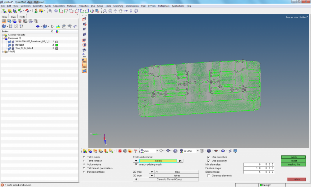
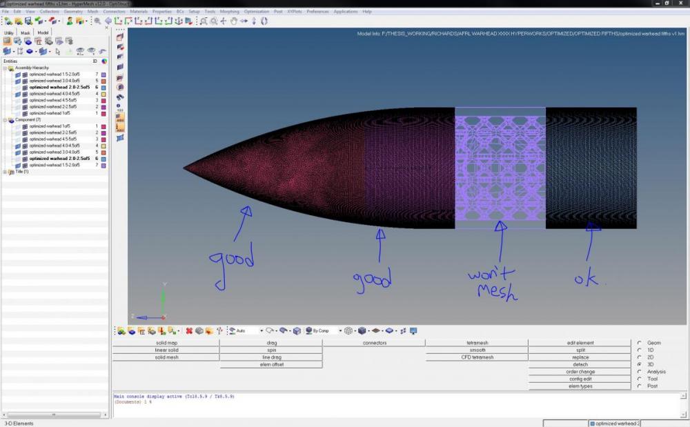
I'm still having issues. I've been trying splitting the part up into multiple sections. Some of them mesh just fine (they don't even have a surface mesh - right to the 3D tetramesh). Some creat a 2D surface mesh and then automatically generate the 3D mesh I want. Some have the same errors we've discussed above. There doesn't seem to be any correlation between the part and the meshing issues. With some errors HyperMesh itself is crashing and I need to restart.
I have tried searching for and equivalencing free edges (this doesn't appear to work. I don't have an ^edges component).
I have tried using the 2D boundary mesh to generate a subsequent 3D tetramesh.
I am also having issues where components that I was able to mesh in on .hm file are not meshing in a new .hm file even though I am doing to exact same thing to them. (because I am trying to reduce my file size. What works with 0.25 size elements does not not with 0.500 size elements!)
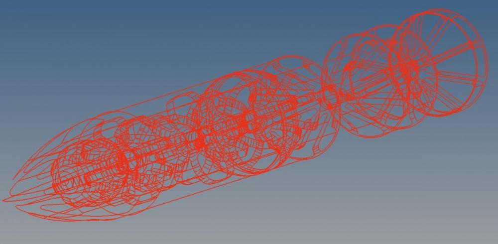
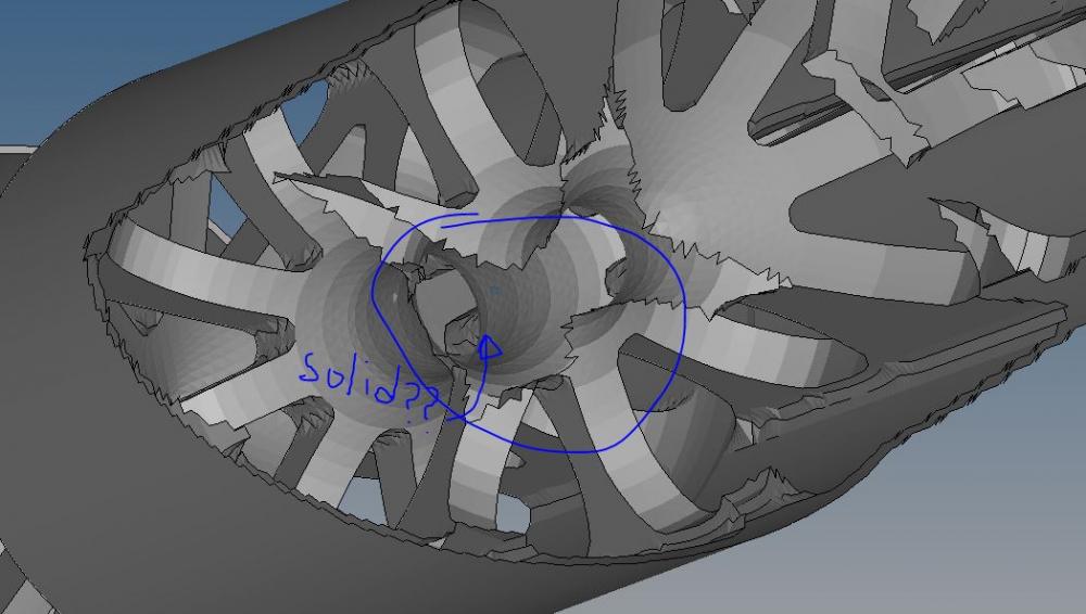
I know I haven't given you guys much to work with but I could really use some help if possible. I have attached a picture and the .hm file (in a .zip).
Thanks, Hayden
0 -
Is it possible to get additional help on this topic? I am trying to figure out why trying the exact same process works in some cases and doesn't in others.
0 -
-
Hi
Confirm length unit of your geometry and reduce mesh size or scale model up
0


.thumb.png.2a410ef4f2532452b2b04515743827e9.png)
.thumb.png.037b002a5ae6db067e4647867184bc02.png)