CBUSH SPRING

Altair Forum User
Altair Forum User
Altair Employee
edited October 2020 in Community Q&A

Hello everbody,


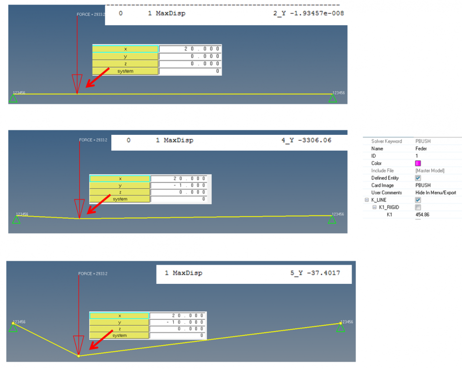
in the following picture you see 3 examples of a spring (CBUSH). The only difference is, that the node in the middle (were the force is) has different coordinates in each example.

I don´t understand why the Results are so different.

In example one (on top of the picture) the result is nearly 0

In example two ( in the middle of the picture) the node is -1 in y-coordinate and the difference is huge!! There the max displcement in Y is -3306


I have absolut no explanation for that.

Thanks for helping :)/emoticons/default_smile.png' srcset='/emoticons/smile@2x.png 2x' title=':)' width='20' />


<?xml version="1.0" encoding="UTF-8"?>image.thumb.png.41e0c5d608a77a2e61de6782e7add30e.png
Tagged:

Answers

  • tinh
    tinh Altair Community Member
    edited September 2017

    We don't, either :rolleyes:/emoticons/default_rolleyes.gif' title=':rolleyes:' />. Please send us your *.fem file

  • Altair Forum User
    Altair Forum User
    Altair Employee
    edited November 2020

    Here are the three examples, shown in the picture

    Unable to find an attachment - read this blog

  • Altair Forum User
    Altair Forum User
    Altair Employee
    edited November 2020
  • Altair Forum User
    Altair Forum User
    Altair Employee
    edited October 2017

    Do you know what the problem could be?

  • tinh
    tinh Altair Community Member
    edited October 2017

    I am sorry. I was busy. Tomorrow i will check.

    Hoping someone will help you fix it soon

  • Altair Forum User
    Altair Forum User
    Altair Employee
    edited October 2017

    Hi @marvin1991 Did you provide any CID for CBUSH elements? If not can you keep it zero by card editing the elements and check if this helps.

  • Altair Forum User
    Altair Forum User
    Altair Employee
    edited October 2017

    With CID set to zero

    <?xml version="1.0" encoding="UTF-8"?>Marvin.PNG

  • Altair Forum User
    Altair Forum User
    Altair Employee
    edited October 2017

    But your result is not making sense or? You have the highest displacement at the constrainsts. But the force is in the middle, between the springs. And even inthe middle the displacment is 1,9*10^-9 in the girst example. Thats nearly 0 ..

  • Altair Forum User
    Altair Forum User
    Altair Employee
    edited October 2017

    Yes that is because of the I made the CBUSH rigid just to check if this is valid. 


    Without CID solver gave a random displacement and with CID set to zero it is giving expected results. 


    it is recommended that another CID be selected to define the element x-axis.

  • Altair Forum User
    Altair Forum User
    Altair Employee
    edited October 2017

    okay thanks.

    But when i increase the force and lower the K1 factor the displacement is still nearly 0 ..but why?

    Can you tell me how to define the elemet x-axis? I have never done that before. Maybe you can send me a little example?

    Thanks for helping!! :)/emoticons/default_smile.png' srcset='/emoticons/smile@2x.png 2x' title=':)' width='20' />

  • Altair Forum User
    Altair Forum User
    Altair Employee
    edited October 2017

    Hi Marvin,


    I did not notice the K1 factor and load change. I will check this. 


    You can create a local system and set the local system to elements. 

  • Altair Forum User
    Altair Forum User
    Altair Employee
    edited October 2017

    @marvin1991


    This is with a local system and apply stiffness in right direction

    <?xml version="1.0" encoding="UTF-8"?>Marvin.PNG

  • Altair Forum User
    Altair Forum User
    Altair Employee
    edited October 2017

    Awesomme! That looks good :)/emoticons/default_smile.png' srcset='/emoticons/smile@2x.png 2x' title=':)' width='20' />

    Is it possible to send me that model?