Incorrect output (or at least confusing documentation) from space vector generator(Quadrature Control)32?
Submitted by murthyakella on Fri, 03/30/2012 - 21:11
Hi,
I have a question about outputs from space vector generator(Quadrature Control)32. I think it is giving incorrect values.
1) Consistent error with Vissim output values: Vissim output= 1-(2*actual output)
Consider the following case with inputs: U_alpha=1 and U_beta = 0
Expected output:
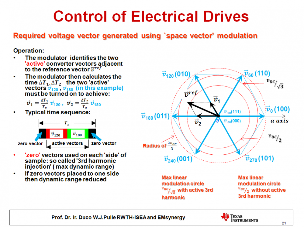
To get this voltage, I should be using just U1 vector(in first quadrant) and zero vectors. Hence, according to the basic space vector modulation equation, U1 has to be switched on for (sqrt(3)/2) time of the total sample duration. Similarly U2 has to be switched on for (0) time of the total sample duration and the null vectors U0 and U7 have to be switched on for the remaining (1-sqrt(3)/2) time of the total sample duration. i.e. t1=0.8666; t2=0; t3=0.134. Similarly, ON duty cycles of PWM a, PWM b and PWM c are (1-0.067), (1-0.933) and (1-0.933) respectively.
Obtained output:
The result for duty cycles obtained with vissim is (-0.866025, 0.866025 and 0.866025). Clearly, not equal to the expected result. Note that Vissim output= 1-(2*actual output)
Consider another case with inputs: U_alpha=0.866025 and U_beta = 0.5
Expected output:
To get this voltage, I should be using U1 and U2 vectors(in first quadrant) and zero vectors. Hence, according to the basic space vector modulation equation, U1 has to be switched on for (1/2) time of the total sample duration. Similarly U2 has to be switched on for (1/2) time of the total sample duration and the null vectors U0 and U7 have to be switched on for the remaining (0) time of the total sample duration. i.e. t1=0.5; t2=0.5; t3=0.5. Similarly, ON duty cycles of PWM a, PWM b and PWM c are (1-0), (1-0.5) and (1-1) respectively.
Obtained output:
The result for duty cycles obtained with vissim is (-1, 0 and 1). Clearly, it is not equal to the expected result. Note that the Vissim output= 1-(2*actual output)
2) Further probable documentation error with TI code:
Code generation for vissim for this particular block indicates that this block calls the texas instruments code. However I notice a small error in their documentation. Their duty times ta, tb and tc are misleading. These refer to the ratio of OFF times to total sampling of PWM top branch which is opposite to the conventional notation of duty cycles which refer to ON durations. For example consider duty cycles of PWM a, PWM b and PWM c as(0.067), (0.933) and (0.933). This respectively instead of (1-0.067), (1-0.933) and (1-0.933). Note that TI output= 1-actual output. The SVMQM code in Texas Instruments Software Library can be found from its control suite software installation. Its older version can also be found at http://www.ti.com/lit/ug/spru485a/spru485a.pdf
Could you please let let me know if there is a mistake in this vissim block? Also does this problem occur only with trial versions? Where can I get correct block or information?
Regards,
Murthy
P.S: I use FMS28335 micoprocessor and a trial version of vissim(8.0).
Answers
-
Submitted by Duco Pulle on Sun, 04/01/2012 - 21:01.
Okay this is a common problem and has to do with how TI defines 100% modulation. Lets consider above case Valpha=1 Vbeta=0. To take a real-world example DC bus voltage of, say, 100V, this would mean a Valpha vector of 57.73 V and Vbeta=0. Note that the corresponding R,S,T phase voltages for this case would be VR= 57.73, VS= -28.86 and VT= -28.86 V, assuming amplitude invariant space-vector notation. Naturally these would not fit in the available voltage window of +- 50V, given the 100V bus we use in our example, so we apply 'pulse centering' (see my book 'Advanced Electrical Drives', which uses power invariant notation) to these three voltages and do the following: we subtract(max+min)/2 from all three, which means, in this case, that we subtract -14.43 V from all three.
The 'corrected' voltages therefore become: VR= 43.3 V, VS= -43.3 V and VT= -43.3V. or in terms of modulation index, taking Vphase/50, gives mR= 0.866, ms= -0.866, mT= -0.866 as VisSim indeed correctly generates. So with pulse centering we can in fact over modulate by a factor 2/sqrt(3)=1.15 which in TI terms is defined as 100%.
One can easily apply the above reasoning to the other case discussed.
Hope this helps, so no worries: VisSim is okay when it come to calculating the correct modulation indexes.
Regards,
Duco--
Prof. Dr. ir. D.W.J.Pulle0
