There may be a couple reasons for wanting to define a custom joint in Inspire Motion. One reason is that a user may wish to prevent (or allow) movement in any one or more of the (6) DOF available. Another reason is if the auto-joint detection fails to detect the desired candidate entities for creating a joint, the user can accept any of the joint types offered and quickly customize it to define the joint type they intended.
Triad Manipulator and Motion Rates:
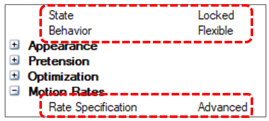
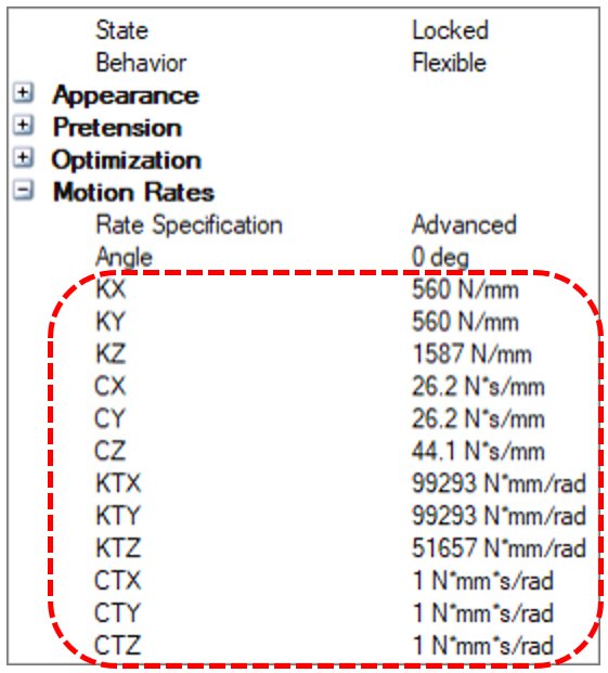
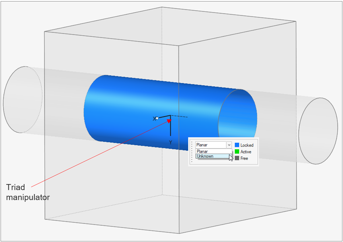
Each joint has its own local reference frame which gets created when the joint is defined. This local reference axis is only visible (as a triad manipulator) to the user when joint State = Locked, Behavior = Flexible, and Rate Specification = Advanced. The directions shown by the axes of the triad correspond to the “Motion Rate” directions in the Property Editor.

Since it is a flexible joint, it is actually modeled as a stiff bushing in the solver, and there are (6) DOF allowed (see: What it means to have “Flexible” joints in Inspire Motion). These (6) DOF correspond to the Motion rates, which define the linear and rotational stiffness and damping properties for the individual directions of the joint. Note: In MotionView, this joint configuration is equivalent to a “compliant” joint.

Re-orienting the Triad:
The triad’s X and Y axes can be re-oriented by clicking on the bubble on the tip of the axis, holding down the mouse button, and hovering the mouse cursor over an entity that could be used as a reference to align the axis. When this is done, the user will see the triad snapping to align with the reference direction. The Z axis cannot be re-oriented, and the triad location cannot be changed. The orientations can also be changed from the Property Editor by changing the Angle under the Motion Rates settings.
Example
Taking all of this into consideration, what if the intent is to turn an “unknown” joint type into a cylindrical joint? A cylindrical joint has (2) Total allowed DOF, 1 rotation and 1 translation.

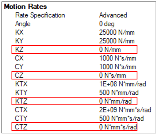
The Flexible joint Motion rates for a custom cylindrical joint can be specified as follows:

When attempting to prevent one of the DOF from moving in a customized joint, a high stiffness (and damping) can be assigned to that DOF. Notice in the image above that the stiffness and damping for all directions except the Z directions are using a larger value, which prevents movement in those DOF. When the joint is first tuned into an Advanced joint type, default stiffness and damping values are used, and are typically good enough to prevent a DOF from moving. If the intent is to allow full motion on a particular DOF, a value of 0 can be assigned to the stiffness and damping fields for that particular direction.
Additional Notes:
- When a joint is created, behind the scenes there are two markers created, one representing the action body and one representing the reaction body. Therefore, if the joint is, for example, between a moving part and ground, when the joint experiences motion, one marker moves with the moving body and the other remains fixed with ground. Therefore, it is possible that the user may need to use the “Flip Order” option for the joint, found in the Property Editor.

- Wherever the visual triad is located is where the joint is positioned. Since the joint is dependent on the geometry, the position cannot be changed unless geometry is changed. Depending on the features available when the baseline joint is created, the triad may not be centered at the exact physical center of the joint. When this happens, it may be necessary to manipulate the geometry in the region to help relocate the joint.
- If there is no geometry available to create the baseline joint to start with, then Inspire Geometry tools can be used to quickly create one or more bodies to use as a joint detection, or an unknown joint can be created and then customized.
Example Model:
An example model showing the use of a custom joint is attached to this blog. The joint represents what is known as in-line joint, where there are (3) rotational DOF and 1 translational DOF. Open the model and solve. A warning message about Deformation Sensors being disabled will appear. This is ok. Select Continue on the warning message. The sensor was turned off intentionally for this example (Run Settings --> Advanced --> Model Checking --> Sensors).