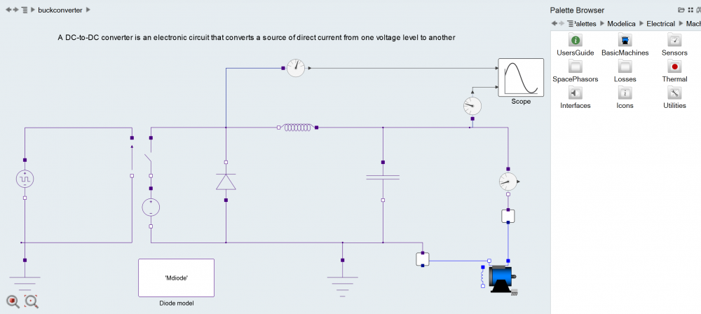
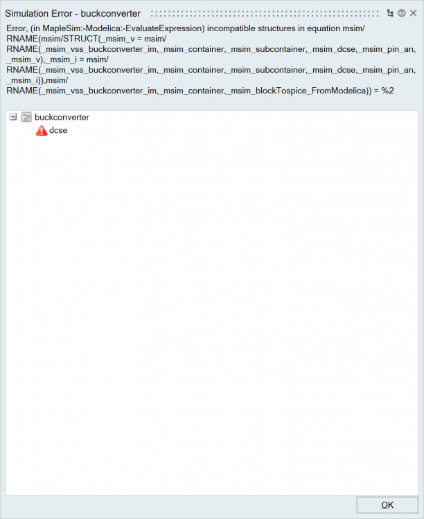
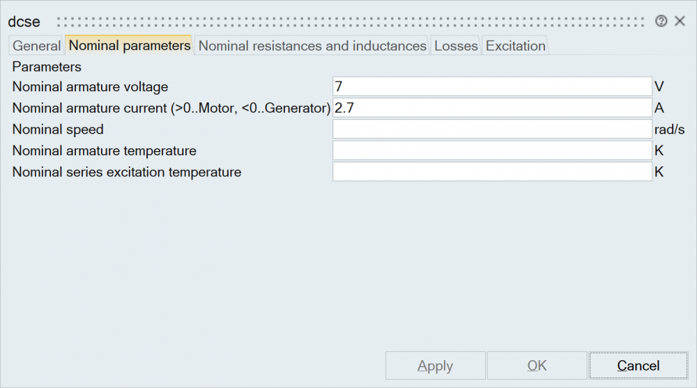
simulating a buck converter with a dc motor load
Answers
-
Hi Leow,
I did not reach with the exact motor you have (but probably because I am not familar with motors). But I made a simple testcase to explain how you can pass the current from the spice side to the modelica one.
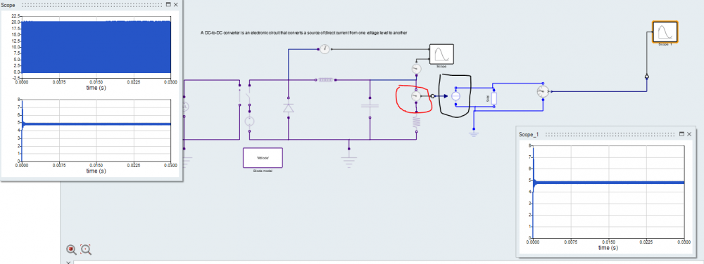
On the red circle on the picture below, you will see that I put a current sensor (coming from the HyperSpice palett). This sensor is used to extract and convert an Spice current into a Signal (Activate signal). Then you can put a currentSignal source from the modelica palett (Modelica/Electrical/Analog/sources), to transform the Activate signal into a Modelica current. After that operation, you can add your modelica circuit as you need.
Here on the picture below I just put a simple resistor to show you the way to make it works. You can see that the voltage on the modelica resistor is the same than the voltage on the resistor from the HyperSpice side and the simulation is fine.
You can use similar method for your motor.
Regards,
Philippe
0


