Overview
(This is a translated version of a blog, posted by Kosuke Ikeda. The original blog in Japanese can be found here).
With this example we show how to transfer a linear model from OptiStruct into Activate.
Using OptiStruct's CMS (Component Mode Synthesis), we will output a matrix with reduced degrees of freedom from OptiStruct and import it into Activate.
Pre-Requisite
You can download the file from the following link.
dmigpch_reader_ABCD.zip
Usage/Installation Instructions
Model Overview
The model consists of a iron plate supported by bushings on four corners. Viscous damping is set on the bushings at all corners thus creating a damping matrix.
Additionally, Structural Damping GE is set in the material parameters of the steel plate thus creating imaginary (i) on the stiffness matrix.
Structural Damping is by default ignored in the transient analysis response unless param, w4 is specified. In this example we set param,w4,1000 which converts the structural damping into an equivalent viscous damping with a frequency of interest of 1000 rads/s.
More info about Structural damping can be found in the post.
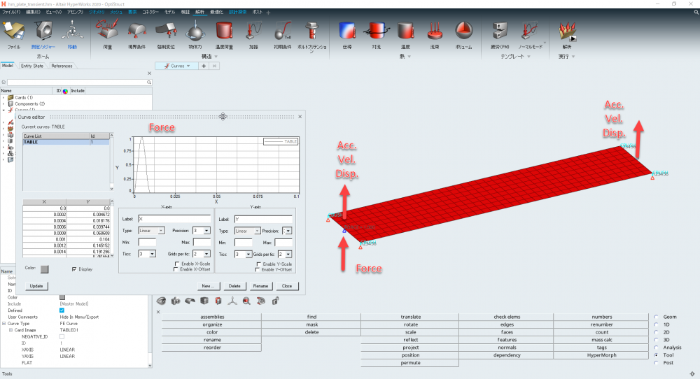
Next we give a Force impulse input at the on end of the plate end check the displacement, velocity and acceleration on the points opposite to the excitation.
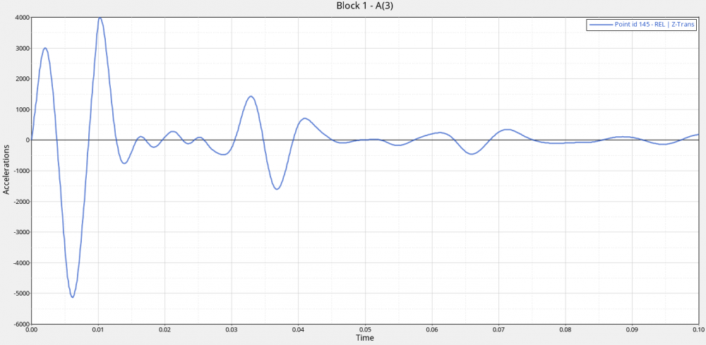
The acceleration response history of the excitation point is shown on the next graph.
Mass Damping Stiffness (MCK) Matrix Output
In the example bellow the hm_plate_cms.fem file is used.
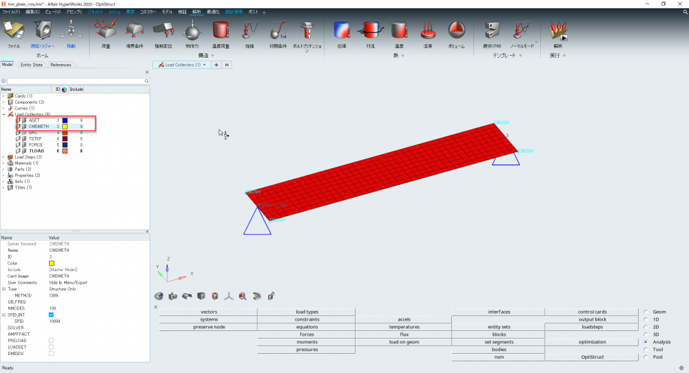
CMSMETH’s GBN method reduces the overall degrees of freedom. The number of modes kept was set to 100.
We then specifiy the Z degrees of freedom of both ends of the input / output nodes in the ASET card.
Next to export the MCK matrix in an ASCII file format, param,extout,dmigpch is defined.
When the calculation is finished, an ASCII file with the output matrix is generated.
Creating a State Matrix (ABCD Matrix)
The output from the procedure described above is a MCK matrix, which must be converted to an ABCD matrix before it can be imported into Activate.
The conversion is processed within Altair Compose by using the existing DMIGPC reader. The process is explained on the following post.
Read M, K and C matrices and compute energy of each DOF - Compose - Altair Products - Altair Community
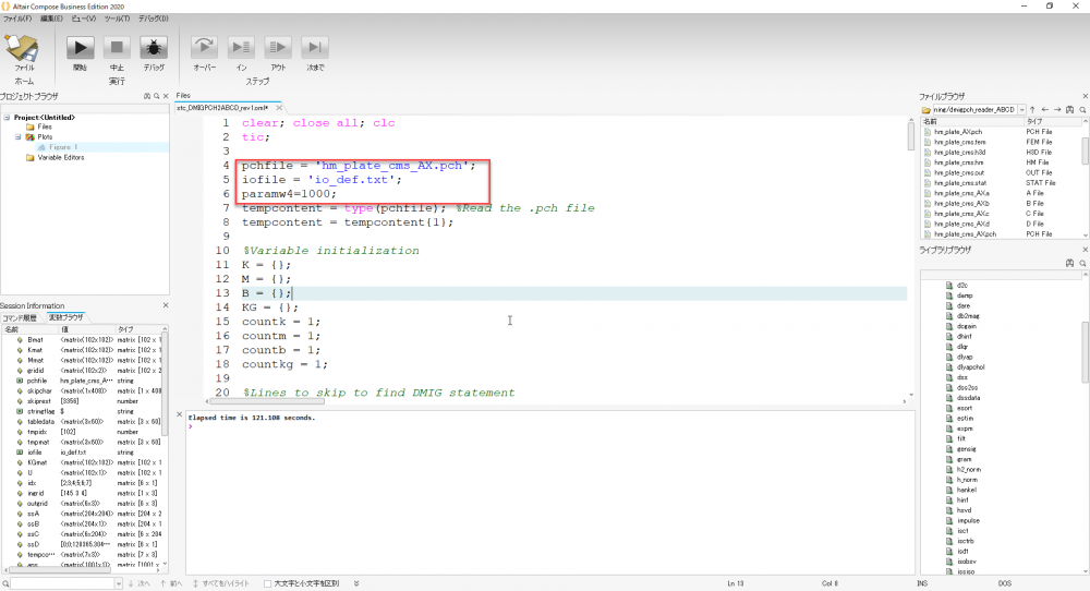
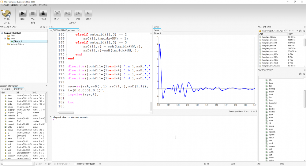
In lines 4 to 6 the OptiStruct pchfile is specified along with the input/output definition file and the frequency of interest damping conversion parameter param,w4.
This section describes the input/output definition file (io_def.txt).
Column 1: Node ID
Column 2: Degrees of freedom
Column 3: Specify displacement, velocity, acceleration, and load. 1: Displacement, 2: Velocity, 3: Acceleration, 4: Load. To create an ABCD matrix, you must define the input/output degrees of freedom. If it is 4, it will be the input point. In the case of 1~3, it will be the output point. The number can be arbitrary. It supports multiple inputs and outputs.
145,3,4
145,3,1
145,3,2
145,3,3
193,3,1
193,3,2
193,3,3
Compose generate files including the ABCD matrices in .a, .b, .c, and .d.
Also, impulse responses can be calculated easily on Compose, so only the impulse responses of the first input and first output are plotted.
The current directory is where the file browser is open, so set it to the folder where the input file is located.
Import to Activate
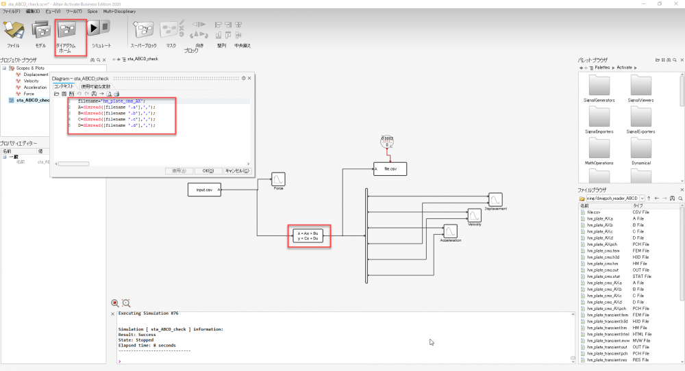
We have prepared a simple model to test: sta_ABCD_check.scm.
In Diagram Home, we go ahead and load the ABCD matrix file.
As with Compose, the current directory is open in the file browser, so set it to the folder where the input file is located.
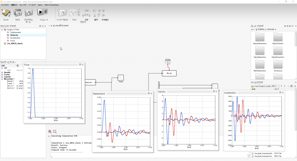
When the model is run, the displacement, velocity, and acceleration results of both ends relative to the impulse input are plotted on Activate.
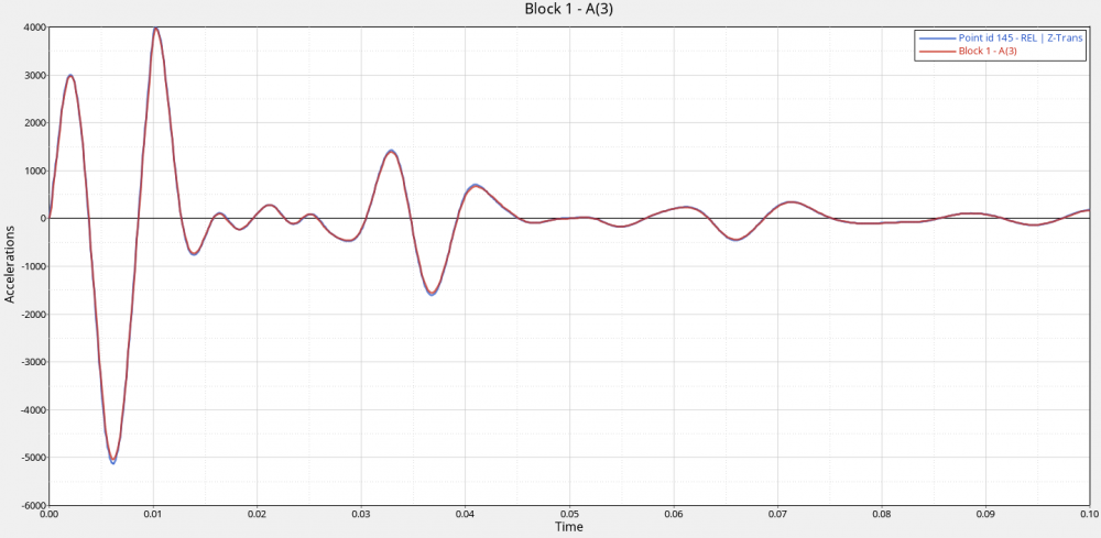
Finally, the results are written out to the file .csv. If we compare it with the OptiStruct results in HyperGraph we observe that they match.
Post-Requisite
Official Website
Altair Activate
Altair OptiStruct
Altair Compose